EUV light source collector erosion mitigation
US20060289808A1
2006-12-28
11/238,828
2005-09-28
✅ Patent granted
US 7,180,083 B2
2007-02-20
-
-
Jack Berman | Jennifer Yantorno
2025-09-28
Abstract:
An EUV light source collector erosion mitigation system and method is disclosed which may comprise a collector comprising a multilayered mirror collector comprising a collector outer surface composed of a capping material subject to removal due to a removing interaction with materials created in an EUV light-creating plasma; a replacement material generator positioned to deliver replacement material comprising the capping material to the collector outer surface at a rate sufficient to replace the capping material removed due to the removing interaction. The replacement material generator may comprise a plurality of replacement material generators positioned to respectively deliver replacement material to a selected portion of the collector outer surface, which may comprise a sputtering mechanism sputtering replacement capping material onto the collector outer surface.
Inventors:
- Igor V. Fomenkov 115 🇺🇸 San Diego, CA, United States
- William N. Partlo 113 🇺🇸 Poway, CA, United States
- Alexander I. ERSHOV 67 🇺🇸 San Diego, CA, United States
Assignee:
- CYMER, INC. 273 🇺🇸 San Diego, CA, United States
Interested in similar patents?
Get notified when new applications in this technology area are published.
Classification:
A61N5/06 IPC
Radiation therapy using light
G01J3/10 IPC
Spectrometry; Spectrophotometry; Monochromators; Measuring colours; Details Arrangements of light sources specially adapted for spectrometry or colorimetry
G03F7/70916 » CPC main
Photomechanical, e.g. photolithographic, production of textured or patterned surfaces, e.g. printing surfaces; Materials therefor, e.g. comprising photoresists; Apparatus specially adapted therefor; Exposure apparatus for microlithography; Construction of apparatus, e.g. environment, hygiene aspects or materials; Hygiene, e.g. preventing apparatus pollution, mitigating effect of pollution, removing pollutants from apparatus; electromagnetic and electrostatic-charge pollution Pollution mitigation, i.e. mitigating effect of contamination or debris, e.g. foil traps
B82Y10/00 » CPC further
Nanotechnology for information processing, storage or transmission, e.g. quantum computing or single electron logic
G03F7/70033 » CPC further
Photomechanical, e.g. photolithographic, production of textured or patterned surfaces, e.g. printing surfaces; Materials therefor, e.g. comprising photoresists; Apparatus specially adapted therefor; Exposure apparatus for microlithography; Production of exposure light, i.e. light sources by plasma EUV sources
G03F7/70175 » CPC further
Photomechanical, e.g. photolithographic, production of textured or patterned surfaces, e.g. printing surfaces; Materials therefor, e.g. comprising photoresists; Apparatus specially adapted therefor; Exposure apparatus for microlithography; Mask illumination systems; Details of optical elements Lamphouse reflector arrangements, i.e. collecting light from solid angle upstream of the light source
G03F7/70983 » CPC further
Photomechanical, e.g. photolithographic, production of textured or patterned surfaces, e.g. printing surfaces; Materials therefor, e.g. comprising photoresists; Apparatus specially adapted therefor; Exposure apparatus for microlithography; Construction of apparatus, e.g. environment, hygiene aspects or materials Optical system protection, e.g. pellicles or removable covers for protection of mask
G21K1/062 » CPC further
Arrangements for handling particles or ionising radiation, e.g. focusing or moderating using diffraction, refraction or reflection, e.g. monochromators Devices having a multilayer structure
H05G2/003 » CPC further
X-ray radiation generated from plasma being produced from a liquid or gas
H05G2/003 » CPC further
X-ray radiation generated from plasma being produced from a liquid or gas
G01J1/429 » CPC further
Photometry, e.g. photographic exposure meter using electric radiation detectors applied to measurement of ultraviolet light
G21K2201/067 » CPC further
Arrangements for handling radiation or particles using diffractive, refractive or reflecting elements Construction details
H01J61/62 IPC
Gas-discharge or vapour-discharge lamps Lamps with gaseous cathode, e.g. plasma cathode
Description
CROSS-REFERENCE TO RELATED APPLICATIONSThe present application is a continuation-in-part of U.S. patent application Ser. No. 11/174,442, entitled SYSTEMS AND METHODS FOR REDUCING THE INFLUENCE OF PLASMA-GENERATED DEBRIS ON THE INTERNAL COMPONENTS OF AN EUV LIGHT SOURCE, filed on Jun. 29, 2005, and Ser. No. 11/168190, entitled filed on Jun. 27, 2005, the disclosures of which are hereby incorporated by reference.
FIELD OF THE INVENTIONThe present invention related to LPP EUV light source collector erosion mitigation.
BACKGROUND OF THE INVENTIONExperiments have shown that extreme ultraviolet (“EUV”) light sources, e.g., produced by a laser produced plasma (“LPP”), using a metal such as tin for a plasma source material suffers from erosion of the primary collector mirror. This erosion is due to, e.g., sputtering by energetic source material ions, e.g., tin ions and neutrals created by the LPP. Applicants propose apparatus and methods for addressing this issue.
SUMMARY OF THE INVENTIONAn EUV light source collector erosion mitigation system and method is disclosed which may comprise a collector comprising a multilayered mirror collector comprising a collector outer surface composed of a capping material subject to removal due to a removing interaction with materials created in an EUV light-creating plasma; a replacement material generator positioned to deliver replacement material comprising the capping material to the collector outer surface at a rate sufficient to replace the capping material removed due to the removing interaction. The replacement material generator may comprise a plurality of replacement material generators positioned to respectively deliver replacement material to a selected portion of the collector outer surface, which may comprise a sputtering mechanism sputtering replacement capping material onto the collector outer surface. The system and method may further comprise an EUV light detector providing an indication of the EUV reflectivity of the collector; and a replacement material generator control mechanism controlling the delivery of replacement material to the collector outer surface, which may comprise controlling the rate of delivery of the replacement material.
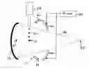
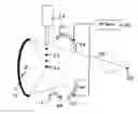
BRIEF DESCRIPTION OF THE DRAWINGSFIG. 1 shows schematically an example of an EUV light source plasma initiation site and associated EUV light collector according to aspects of an embodiment of the present invention.
DETAILED DESCRIPTION OF PREFERRED EMBODIMENTSIn order to achieve a commercially viable collector lifetime applicants propose apparatus and methods for addressing the erosion by, according to aspects of embodiments of the present invention, e.g., replacing the material in-situ within the plasma production chamber during operation of the LPP EUV light source.
According to aspects of an embodiment of the present invention and apparatus and method for replacing eroded mirror material can involve, e.g., the installation of sputter sources around the parameter of the collector assembly that, e.g., can continuously provide mirror coating material, e.g., at a rate equal to the removal rate due to sputtering from the plasma source material, e.g., tin sputtering or other sputtering. An exemplary configuration is shown schematically in FIG. 1.
Turning now to FIG. 1 there is shown that several sputter sources can be placed such that they, e.g., provide full coverage of the collector mirror and, e.g., produce a combined deposition rate profile across the mirror surface that is equal to the erosion rate profile across the mirror surface.
A proper deposition rate of the sputter sources separately and collectively must be carefully selected. According to aspects of an embodiment of the present invention one method for doing so could be to characterize the erosion profile of an unprotected mirror and, e.g., produce a static deposition profile to match, with the required control over the deposition profile being such that the net material removal rate approaches almost perfectly zero.
As an alternative, according to aspects of an embodiment of the present invention one might use an in-situ metrology to provide a feed-back control for the deposition rate. By way of an example of such a system, and assuming, e.g., that the deposited material is to be molybdenum, the EUV reflectivity of an EUV mirror will, e.g., start to decrease as the top layer thickness of molybdenum increases beyond a certain limit, e.g., due to the sputtering from the controlled molybdenum sputtering sources. Since these EUV mirrors will have a large number of layers, there is little or no change in reflectivity with the loss of one or two mirror layers. One could, therefore, according to aspects of an embodiment of the present invention, monitor the EUV reflectivity in-situ and deposit molybdenum until the reflectivity drops by a selected amount, e.g., a few percent or perhaps even less, within some tolerances for the metrology to measure relatively accurately and also within some bounds of ability to sacrifice reflectivity and still maintain a desired energy output. According to aspects of an embodiment of the present invention the output EUV light energy if the entire system, e.g., as delivered to the intermediate focus as discussed below, may be used as such a measure of reflectivity or individual EUV detectors, as discussed below may be positioned to detect reflectivity changes of selected portions of the collector.
Then, as the EUV source is operated and plasma source material sputtering, e.g., tin sputtering begins removing molybdenum from the mirror surface the mirror reflectivity begins to increase back to its uncoated value. This increase, e.g., can be monitored and used as a feed-back for the sputter coating rate of molybdenum. The metrology may comprise a plurality of detectors sampling different portions of the collector surface and/or a plurality of witness plates positioned to simulate erosion at differing locations of the collector surface.
As shown schematically and by way of example in FIG. 1, an LPP EUV light source 10 may comprise an EUV light collector 12. Plasma source material, e.g., tin or lithium, may be delivered to a plasma initiation site 20 in the form of target droplets 22, delivered from a target droplet generator 24. The target droplets, in turn, may be irradiated, e.g., by a laser beam (not shown) to form a plasma which emits EUV light, e.g., at about 13.5 nm wavelength. The collector 12 may comprise an elliptically shaped multilayer mirror for reflecting EUV light with a focus of the ellipse forming the mirror shape at the plasma initiation site 20 and focus a cone of EUV light 30 to an intermediate focus 32 at the second focus of the ellipse, where, e.g., the EUV light may be delivered to a device utilizing the light, e.g., an integrated circuit manufacturing process photolithography apparatus (not shown).
A plurality of replacement material delivering devices 40, two of which are shown by way of illustration in FIG. 1, may be positioned outside of the cone 30 to deliver replacement material, e.g., molybdenum to the outer surface 14 of the multilayer mirror forming the collector 12. The replacement material delivery devices 40 may comprise an apparatus for sputtering the replacement material, e.g., molybdenum onto at least some portion of the collector 12 outer surface 14, such as a “Torus” Magnetron Sputterer Source, made by Kurt T. esker Company of Pittsburgh, P.A. The sputtering mechanism 40 may be provided with an RF source 50, which may be part of the sputtering mechanism 40 to drive the rate of sputtering by the sputtering mechanism 40 and thus the rate of delivery of the replacement material to the collector 12 outer surface 14.
EUV light intensity detectors 60, such as a model XUV100 made by International Radiation Detectors, Inc. of Torrance, Calif. may be positioned to detect changes in reflectivity from a selected portion of the collector 12 outer surface 14.
While the particular aspects of embodiment(s) of the EUV LIGHT SOURCE COLLECTOR EROSION MITIGATION described and illustrated in this patent application in the detail required to satisfy 35 U.S.C. § 112 is fully capable of attaining any above-described purposes for, problems to be solved by or any other reasons for or objects of the aspects of an embodiment(s) above described, it is to be understood by those skilled in the art that it is the presently described aspects of the described embodiment(s) of the present invention are merely exemplary, illustrative and representative of the subject matter which is broadly contemplated by the present invention. The scope of the presently described and claimed aspects of embodiments fully encompasses other embodiments which may now be or may become obvious to those skilled in the art based on the teachings of the Specification. The scope of the present EUV LIGHT SOURCE COLLECTOR EROSION MITIGATION is solely and completely limited by only the appended claims and nothing beyond the recitations of the appended claims. Reference to an element in such claims in the singular is not intended to mean nor shall it mean in interpreting such claim element “one and only one” unless explicitly so stated, but rather “one or more”. All structural and functional equivalents to any of the elements of the above-described aspects of an embodiment(s) that are known or later come to be known to those of ordinary skill in the art are expressly incorporated herein by reference and are intended to be encompassed by the present claims. Any term used in the specification and/or in the claims and expressly given a meaning in the Specification and/or claims in the present application shall have that meaning, regardless of any dictionary or other commonly used meaning for such a term. It is not intended or necessary for a device or method discussed in the Specification as any aspect of an embodiment to address each and every problem sought to be solved by the aspects of embodiments disclosed in this application, for it to be encompassed by the present claims. No element, component, or method step in the present disclosure is intended to be dedicated to the public regardless of whether the element, component, or method step is explicitly recited in the claims. No claim element in the appended claims is to be construed under the provisions of 35 U.S.C. § 112, sixth paragraph, unless the element is expressly recited using the phrase “means for” or, in the case of a method claim, the element is recited as a “step” instead of an “act”.
It will be understood by those skilled in the art that the aspects of embodiments of the present invention disclosed above are intended to be preferred embodiments only and not to limit the disclosure of the present invention(s) in any way and particularly not to a specific preferred embodiment alone. Many changes and modification can be made to the disclosed aspects of embodiments of the disclosed invention(s) that will be understood and appreciated by those skilled in the art. The appended claims are intended in scope and meaning to cover not only the disclosed aspects of embodiments of the present invention(s) but also such equivalents and other modifications and changes that would be apparent to those skilled in the art. In additions to changes and modifications to the disclosed and claimed aspects of embodiments of the present invention(s) noted above others could be implemented.
Claims
I/We claim:1. An EUV light source collector erosion mitigation system comprising:
a collector comprising a multilayered mirror collector comprising a collector outer surface composed of a capping material subject to removal due to a removing interaction with materials created in an EUV light-creating plasma;
a replacement material generator positioned to deliver replacement material comprising the capping material to the collector outer surface at a rate sufficient to replace the capping material removed due to the removing interaction.
2. The apparatus of claim 1 further comprising:
the replacement material generator comprises a plurality of replacement material generators positioned to respectively deliver replacement material to a selected portion of the collector outer surface.
3. The apparatus of claim 1 further comprising:
the replacement material generator comprises a sputtering mechanism sputtering replacement capping material onto the collector outer surface.
4. The apparatus of claim 2 further comprising:
the replacement material generator comprises a sputtering mechanism sputtering replacement capping material onto the collector outer surface.
5. The apparatus of claim 1 further comprising:
an EUV light detector providing an indication of the EUV reflectivity of the collector;
a replacement material generator control mechanism controlling the delivery of replacement material to the collector outer surface.
6. The apparatus of claim 2 further comprising:
an EUV light detector providing an indication of the EUV reflectivity of the collector;
a replacement material generator control mechanism controlling the delivery of replacement material to the collector outer surface.
7. The apparatus of claim 3 further comprising:
an EUV light detector providing an indication of the EUV reflectivity of the collector;
a replacement material generator control mechanism controlling the delivery of replacement material to the collector outer surface.
8. The apparatus of claim 4 further comprising:
an EUV light detector providing an indication of the EUV reflectivity of the collector;
a replacement material generator control mechanism controlling the delivery of replacement material to the collector outer surface.
9. The apparatus of claim 5 further comprising:
the replacement material generator controlling mechanism controls the rate of delivery f the replacement material.
10. The apparatus of claim 6 further comprising:
the replacement material generator controlling mechanism controls the rate of delivery f the replacement material.
11. The apparatus of claim 7 further comprising:
the replacement material generator controlling mechanism controls the rate of delivery f the replacement material.
12. The apparatus of claim 8 further comprising:
the replacement material generator controlling mechanism controls the rate of delivery f the replacement material.
13. An EUV light source collector erosion mitigation method for a collector comprising a multilayered mirror collector comprising a collector outer surface composed of a capping material subject to removal due to a removing interaction with materials created in an EUV light-creating plasma, the method comprising:
utilizing a replacement material generator to deliver replacement material comprising the capping material to the collector outer surface at a rate sufficient to replace the capping material removed due to the removing interaction.
Images & Drawings included:
Sources:
- United States Patent and Trademark Office - verify current appl. status at the USPTO↗
Similar patent applications:
Recent applications in this class:
- » 20250291263 2025-09-18
SEMICONDUCTOR PROCESSING TOOL AND METHODS OF OPERATION - » 20250216803 2025-07-03
PASSIVE DUST TRAP, ILLUMINATION SYSTEM, AND LITHOGRAPHY SYSTEM - » 20250147439 2025-05-08
CLEANING APPARATUS, EXTREME ULTRAVIOLET LITHOGRAPHY SYSTEM, AND METHOD OF CLEANING EXTREME ULTRAVIOLET LITHOGRAPHY SYSTEM - » 20250076775 2025-03-06
EXTREME ULTRAVIOLET SOURCE CLEANING APPARATUS, EUV SOURCE CLEANING METHOD USING THE SAME, AND SUBSTRATE PROCESSING METHOD INCLUDING THE SAME - » 20250013159 2025-01-09
CLEANING METHOD, COMPUTER STORAGE MEDIUM, AND SUBSTRATE TREATMENT SYSTEM - » 20240385541 2024-11-21
EUV LITHOGRAPHY SYSTEM HAVING A GAS-BINDING COMPONENT - » 20240385540 2024-11-21
SEMICONDUCTOR PROCESSING TOOL AND METHODS OF OPERATION - » 20240353766 2024-10-24
EXTREME ULTRAVIOLET LITHOGRAPHY SYSTEM - » 20240353765 2024-10-24
METHOD AND APPARATUS FOR MITIGATING TIN DEBRIS - » 20240353764 2024-10-24
LITHOGRAPHY APPARATUS
Recent applications for this Assignee:
- » 20150083898 2015-03-26
System and method for controlling droplet timing in an LPP EUV light source - » 20140233005 2014-08-21
System and method for adjusting seed laser pulse width to control EUV output energy - » 20140203195 2014-07-24
Thermal monitor for an extreme ultraviolet light source - » 20140191133 2014-07-10
Method of timing laser beam pulses to regulate extreme ultraviolet light dosing - » 20140191132 2014-07-10
Method of timing laser beam pulses to regulate extreme ultraviolet light dosing - » 20140102881 2014-04-17
METHOD OF AND APPARATUS FOR IN-SITU REPAIR OF REFLECTIVE OPTIC - » 20140098413 2014-04-10
Harsh environment optical element protection - » 20140072006 2014-03-13
System and method for seed laser mode stabilization - » 20130329763 2013-12-12
Corrosion resistant electrodes for laser chambers - » 20130322482 2013-12-05
System and method for protecting a seed laser in an EUV light source with a Bragg AOM