Electronic Package and Method of Making an Electronic Package
US20120080787A1
2012-04-05
13/220,733
2011-08-30
Abstract:
An electrical package and a method of forming the electrical package, where the electrical package has a substrate with a frontside, an intergrated circuit coupled to the frontside of the substrate, and at least one non-collapsible metal connector created on the frontside of the first substrate.
Inventors:
- Milind P Shah 12 🇺🇸 San Diego, CA, United States
- Omar J. Bchir 12 🇺🇸 San Diego, CA, United States
- Sashidhar Movva 6 🇺🇸 San Diego, CA, United States
Assignee:
- QUALCOMM INCORPORATED 38,359 🇺🇸 San Diego, CA, United States
Interested in similar patents?
Get notified when new applications in this technology area are published.
Classification:
H01L25/50 » CPC main
Assemblies consisting of a plurality of individual semiconductor or other solid state devices ; Multistep manufacturing processes thereof Multistep manufacturing processes of assemblies consisting of devices, each device being of a type provided for in group or
H01L21/4853 » CPC further
Processes or apparatus adapted for the manufacture or treatment of semiconductor or solid state devices or of parts thereof; Manufacture or treatment of semiconductor devices or of parts thereof the devices having at least one potential-jump barrier or surface barrier, e.g. PN junction, depletion layer or carrier concentration layer; Manufacture or treatment of parts, e.g. containers, prior to assembly of the devices, using processes not provided for in a single one of the subgroups -; Conductive parts; Leads on or in insulating or insulated substrates, e.g. metallisation Connection or disconnection of other leads to or from a metallisation, e.g. pins, wires, bumps
H01L23/3128 » CPC further
Details of semiconductor or other solid state devices; Encapsulations, e.g. encapsulating layers, coatings, e.g. for protection characterised by the arrangement or shape the device being completely enclosed a substrate forming part of the encapsulation the substrate having spherical bumps for external connection
H01L23/49811 » CPC further
Details of semiconductor or other solid state devices; Arrangements for conducting electric current to or from the solid state body in operation, e.g. leads, terminal arrangements ; Selection of materials therefor consisting of soldered constructions; Leads, on insulating substrates, Additional leads joined to the metallisation on the insulating substrate, e.g. pins, bumps, wires, flat leads
H01L24/97 » CPC further
Arrangements for connecting or disconnecting semiconductor or solid-state bodies; Methods or apparatus related thereto; Batch processes at chip-level, i.e. with connecting carried out on a plurality of singulated devices, i.e. on diced chips the devices being connected to a common substrate, e.g. interposer, said common substrate being separable into individual assemblies after connecting
H01L25/105 » CPC further
Assemblies consisting of a plurality of individual semiconductor or other solid state devices ; Multistep manufacturing processes thereof all the devices being of a type provided for in the same subgroup of groups - , e.g. assemblies of rectifier diodes the devices having separate containers the devices being of a type provided for in group
H01L24/48 » CPC further
Arrangements for connecting or disconnecting semiconductor or solid-state bodies; Methods or apparatus related thereto; Means for bonding being attached to, or being formed on, the surface to be connected, e.g. chip-to-package, die-attach, "first-level" interconnects; Manufacturing methods related thereto; Wire connectors; Manufacturing methods related thereto; Structure, shape, material or disposition of the wire connectors after the connecting process of an individual wire connector
H01L25/0655 » CPC further
Assemblies consisting of a plurality of individual semiconductor or other solid state devices ; Multistep manufacturing processes thereof all the devices being of a type provided for in the same subgroup of groups - , e.g. assemblies of rectifier diodes the devices not having separate containers the devices being of a type provided for in group the devices being arranged next to each other
H01L25/0657 » CPC further
Assemblies consisting of a plurality of individual semiconductor or other solid state devices ; Multistep manufacturing processes thereof all the devices being of a type provided for in the same subgroup of groups - , e.g. assemblies of rectifier diodes the devices not having separate containers the devices being of a type provided for in group Stacked arrangements of devices
H01L2224/83102 » CPC further
Indexing scheme for arrangements for connecting or disconnecting semiconductor or solid-state bodies and methods related thereto as covered by; Methods for connecting semiconductor or other solid state bodies using means for bonding being attached to, or being formed on, the surface to be connected using a layer connector the layer connector being supplied to the parts to be connected in the bonding apparatus using surface energy, e.g. capillary forces
H01L2225/06555 » CPC further
Details relating to assemblies covered by the group but not provided for in its subgroups; All the devices being of a type provided for in the same subgroup of groups - the devices not having separate containers the devices being of a type provided for in group; Stacked arrangements of devices Geometry of the stack, e.g. form of the devices, geometry to facilitate stacking
H01L2225/1023 » CPC further
Details relating to assemblies covered by the group but not provided for in its subgroups; All the devices being of a type provided for in the same subgroup of groups - the devices having separate containers the devices being of a type provided for in group the containers being in a stacked arrangement the lowermost container comprising a device support the support being an insulating substrate
H01L2225/1058 » CPC further
Details relating to assemblies covered by the group but not provided for in its subgroups; All the devices being of a type provided for in the same subgroup of groups - the devices having separate containers the devices being of a type provided for in group the containers being in a stacked arrangement; Details of electrical connections between containers Bump or bump-like electrical connections, e.g. balls, pillars, posts
H01L2924/01028 » CPC further
Indexing scheme for arrangements or methods for connecting or disconnecting semiconductor or solid-state bodies as covered by; Chemical elements Nickel [Ni]
H01L2924/01029 » CPC further
Indexing scheme for arrangements or methods for connecting or disconnecting semiconductor or solid-state bodies as covered by; Chemical elements Copper [Cu]
H01L2924/01033 » CPC further
Indexing scheme for arrangements or methods for connecting or disconnecting semiconductor or solid-state bodies as covered by; Chemical elements Arsenic [As]
H01L2924/01078 » CPC further
Indexing scheme for arrangements or methods for connecting or disconnecting semiconductor or solid-state bodies as covered by; Chemical elements Platinum [Pt]
H01L2924/01079 » CPC further
Indexing scheme for arrangements or methods for connecting or disconnecting semiconductor or solid-state bodies as covered by; Chemical elements Gold [Au]
H01L2924/014 » CPC further
Indexing scheme for arrangements or methods for connecting or disconnecting semiconductor or solid-state bodies as covered by; Alloys Solder alloys
H01L2924/09701 » CPC further
Indexing scheme for arrangements or methods for connecting or disconnecting semiconductor or solid-state bodies as covered by with a principal constituent of the material being a combination of two or more materials provided in the groups - ; Glass-ceramics, e.g. devitrified glass Low temperature co-fired ceramic [LTCC]
H01L2924/14 » CPC further
Indexing scheme for arrangements or methods for connecting or disconnecting semiconductor or solid-state bodies as covered by; Details of semiconductor or other solid state devices to be connected; Device type Integrated circuits
H01L2924/15331 » CPC further
Indexing scheme for arrangements or methods for connecting or disconnecting semiconductor or solid-state bodies as covered by; Details of package parts other than the semiconductor or other solid state devices to be connected; Die mounting substrate; Connection portion the connection portion being formed on the die mounting surface of the substrate the connection portion being formed both on the die mounting surface of the substrate and outside the die mounting surface of the substrate being a ball array, e.g. BGA
H01L2924/1815 » CPC further
Indexing scheme for arrangements or methods for connecting or disconnecting semiconductor or solid-state bodies as covered by; Details of package parts other than the semiconductor or other solid state devices to be connected; Encapsulation Shape
H01L2224/97 » CPC further
Indexing scheme for arrangements for connecting or disconnecting semiconductor or solid-state bodies and methods related thereto as covered by; Batch processes at chip-level, i.e. with connecting carried out on a plurality of singulated devices, i.e. on diced chips the devices being connected to a common substrate, e.g. interposer, said common substrate being separable into individual assemblies after connecting
H01L2924/15311 » CPC further
Indexing scheme for arrangements or methods for connecting or disconnecting semiconductor or solid-state bodies as covered by; Details of package parts other than the semiconductor or other solid state devices to be connected; Die mounting substrate; Connection portion the connection portion being formed only on the surface of the substrate opposite to the die mounting surface being a ball array, e.g. BGA
H01L2224/92125 » CPC further
Indexing scheme for arrangements for connecting or disconnecting semiconductor or solid-state bodies and methods related thereto as covered by; Methods for connecting semiconductor or solid state bodies including different methods provided for in two or more of groups - ; Specific sequence of method steps; Connecting a surface with connectors of different types; Sequential connecting processes the first connecting process involving a bump connector the second connecting process involving a layer connector
H01L2224/73204 » CPC further
Indexing scheme for arrangements for connecting or disconnecting semiconductor or solid-state bodies and methods related thereto as covered by; Means for bonding being of different types provided for in two or more of groups; Location after the connecting process on the same surface; Bump and layer connectors the bump connector being embedded into the layer connector
H01L2924/00 » CPC further
Indexing scheme for arrangements or methods for connecting or disconnecting semiconductor or solid-state bodies as covered by
H01L2924/181 » CPC further
Indexing scheme for arrangements or methods for connecting or disconnecting semiconductor or solid-state bodies as covered by; Details of package parts other than the semiconductor or other solid state devices to be connected Encapsulation
H01L2924/00012 » CPC further
Indexing scheme for arrangements or methods for connecting or disconnecting semiconductor or solid-state bodies as covered by; Technical content checked by a classifier Relevant to the scope of the group, the symbol of which is combined with the symbol of this group
H01L2224/45099 » CPC further
Indexing scheme for arrangements for connecting or disconnecting semiconductor or solid-state bodies and methods related thereto as covered by; Means for bonding being attached to, or being formed on, the surface to be connected, e.g. chip-to-package, die-attach, "first-level" interconnects; Manufacturing methods related thereto; Wire connectors; Manufacturing methods related thereto; Structure, shape, material or disposition of the wire connectors prior to the connecting process of an individual wire connector; Core members of the connector Material
H01L2924/00014 » CPC further
Indexing scheme for arrangements or methods for connecting or disconnecting semiconductor or solid-state bodies as covered by; Technical content checked by a classifier the subject-matter covered by the group, the symbol of which is combined with the symbol of this group, being disclosed without further technical details
H01L2924/207 » CPC further
Indexing scheme for arrangements or methods for connecting or disconnecting semiconductor or solid-state bodies as covered by; Parameters Diameter ranges
H01L23/498 IPC
Details of semiconductor or other solid state devices; Arrangements for conducting electric current to or from the solid state body in operation, e.g. leads, terminal arrangements ; Selection of materials therefor consisting of soldered constructions Leads, on insulating substrates,
H01L21/56 IPC
Processes or apparatus adapted for the manufacture or treatment of semiconductor or solid state devices or of parts thereof; Manufacture or treatment of semiconductor devices or of parts thereof the devices having at least one potential-jump barrier or surface barrier, e.g. PN junction, depletion layer or carrier concentration layer; Assembly of semiconductor devices using processes or apparatus not provided for in a single one of the subgroups - , e.g. sealing of a cap to a base of a container Encapsulations, e.g. encapsulation layers, coatings
H01L23/48 IPC
Details of semiconductor or other solid state devices Arrangements for conducting electric current to or from the solid state body in operation, e.g. leads, terminal arrangements ; Selection of materials therefor
Description
RELATED APPLICATION
This application claims priority and the benefit of U.S. Provisional application, Ser. No. 61/389,731 filed Oct. 5, 2010.
FIELD OF DISCLOSURE
This disclosure relates generally to integrated circuit packaging, and in particular to package on package systems.
BACKGROUND
Package on Package (“POP”) is a packaging system that allows one IC package to be coupled to another IC package providing more functionality in less space. Signals may be routed through each package.
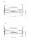
Coupling of IC packages is desirable and may reduce the size of the end user device. FIG. 1A shows an exemplary POP system 100. A first die 104 is mounted onto a first package substrate 108. The package substrate 108 has solder balls 112 on a front side 116 of the package substrate 108. The solder balls 112 provide electrical connectivity to a second substrate package 120 through conducting pads 128. A mold compound 124 is formed over the solder balls 112. A second package 126 is formed over the solder balls and die 104 to form a package on package system.
Disadvantages exist in shrinking the thickness of the bottom package 122. For example, if the height of the solder ball 112 is reduced, the pitch between the solder balls decreases. The pitch is the distance between each solder ball 112. As the pitch decreases, bridging problems with the solder balls occur during reflow of the solder balls 112. Reflow process is applied so that the solder balls 112 provide an attachment mechanism between package to package stacks.
FIG. 1B shows an exemplary POP system 100 after a reflow process is applied. After reflow, bridging may result in electrical shorts 114 and reduce signaling capability between the packages and between the IC die and other surrounding circuits, reducing reliability of the POP system. Another disadvantage of the POP system 100 is that the solder ball attach is generally performed after the IC die 104 is attached to the substrate 108. Because the package system 100 cannot be tested for functionality until after the IC die 104 is attached, the IC die may need to be discarded if the package is found to be not functioning properly. This results in increased expenses.
Therefore, it would be desirable to develop an improved electronic package-on-package system without these disadvantages.
BRIEF DESCRIPTION OF THE DRAWINGS
FIG. 1A is a graphical illustration of a cross-sectional view of a package-on-package system;
FIG. 1B is a graphical illustration of a package-on-package system illustrating solder ball bridging;
FIG. 2 is a flow chart illustrating an exemplary packaging process employing non-collapsible metal connectors that provide electrical connections between packages;
FIG. 3A-3J is a graphical illustration of a cross-sectional view of an exemplary packaging process employing copper cylinder connectors that provide electrical connections between packages;
FIG. 4 is a block diagram showing an exemplary wireless communication system in which it may be advantageous to use a package-on-package system.
DETAILED DESCRIPTION
Inventive aspects are disclosed in the following description and related drawings directed to specific embodiments. Alternate embodiments may be devised without departing from the scope of the invention. Additionally, well-known elements may not be described in detail or may be omitted so as not to obscure relevant details.
The word “exemplary” is used herein to mean “serving as an example, instance, or illustration.” Any embodiment described herein as “exemplary” is not necessarily to be construed as preferred or advantageous over other embodiments. Likewise, the term “embodiments of the invention” does not require that all embodiments include the discussed feature, advantage or mode of operation. The terminology used herein is for the purpose of describing particular embodiments. The described embodiments are to illustrate the teachings of the invention and are not intended to limit the embodiments of the invention described.
Package on package (“POP”) systems may be accomplished through the use of non-collapsible metal connectors in place of solder balls for electrical connection between POP systems. Examples of non-collapsible metals include tin, gold, nickel, chrome and copper. The non-collapsible metals may be formed into three dimensional connector shapes including cylindrical, rectangular, or eliptical shapes. For example, a copper cylinder may be used in place of solder balls for electrical connection between POP systems. However, embodiments of the invention are not so limited to these formations.
Use of non-collapsible metal connectors allows the height of the bottom package to be reduced without reduction of electrical connection reliability. This is because non-collapsible metal may not require the common solder ball reflow process which may spread or widen when reflow occurs. Therefore because non-collapsible metal does not require reflow and does not spread, there is no bridging. Thus electrical reliability is increased. Additionally, non-collapsible metal connectors may allow greater flexibility and reduced costs because whereas solder ball fabrication is generally performed by an assembly house, non-collapsible metal connectors may be formed by the substrate manufacturer. This allows the package to be tested prior to attaching the die and avoids having to discard the die where the package is found not to be functioning properly.
FIG. 2 is a flow chart illustrating an exemplary POP process. A POP process begins at block 202 by receiving a package substrate. FIG. 3A is an illustration of a cross sectional view of an exemplary first package substrate 300. The substrate may be formed from any suitable material, including organic material or inorganic material or a combination of both. For example, the substrate may be formed of glass or silicon or ceramic. At block 204 of FIG. 2, one or more non-collapsible metal connectors are formed, for example, by a lithographic mask and electrolytic plating. FIG. 3A illustrates as an example, copper cylinder connectors 302 formed on the substrate 300 The copper cylinder connectors are formed on the frontside 301 of the substrate 300. FIGS. 3B and 3C illustrate an optional solder cap 304 which may be formed over the copper cylinders 302.
Because the copper cylinder connectors 302 do not themselves reflow, the width, diameter and pitch of the copper cylinder connectors 302 are more easily maintained. Pitch is the distance between each copper cylinder. The height of the copper cylinder connector may be designed independent of pitch considerations. That is, the height of the copper cylinder may be reduced without consideration of the bridging problems suffered by the solder ball connect method. Therefore the height of the copper cylinder may be reduced, even if a tight pitch is desired.
In one embodiment, the copper cylinder connector is designed to have reduced height in order to minimize the size of the package height. For example, the height of the copper cylinder may be at about the same height of an IC die which may be later attached to the substrate. In an alternative embodiment, where the IC die is embedded within the first substrate 300, the height of the copper cylinder may be reduced to the height necessary to make the connection between a first package and a second package. The pitch may be designed independently to the desired number of inputs/outputs between each stacked package. In an exemplary embodiment, the pitch may vary between the copper cylinders 302 as may the actual diameters of the copper cylinders. In another exemplary embodiment, the pitch may be constant between copper cylinders 302. As the pitch shrinks, the diameter of the copper cylinders may shrink to further accommodate a smaller package and maintain a minimum number of input/outputs.
The exemplary process continues at block 206 an IC die is attached to the substrate 300. The term IC die is defined to include any type of IC device, chip or logic device. Any method of die attach may be used, including for example a flip chip, direct die attach, or wire bonding. FIG. 3D is a cross sectional view of an exemplary IC die shown as a flip chip 308 attached to the substrate 300. To provide additional stability to the flip chip 308 attached to the substrate 300, underfill molding 310 may be applied as shown in FIG. 3E. However, the underfill molding 310 may be omitted if not desirable. For example, if wire bonding is used as the IC die attach method at block 206, the underfill molding 310 may be omitted.
After the IC die attach is performed 206, at block 209 either option 1 or option 2 may be selected. If option 1 is selected, at block 210 an overmold 312 may be formed over the copper cylinders 302 and over the optional solder cap 304 to encapsulate the assembly. FIG. 3F is a cross sectional view of the overmold 312 formed over the copper cylinders 302 and IC die 308. If at block 204 the optional solder cap 304 had been formed over the copper cylinder 302, then overmold 312 would also encapsulate the solder cap 304. An alternative embodiment known as flange POP may be used instead. In the flange POP alternative embodiment, the overmold is formed over the IC die 308 only and not the copper cylinders 302 or the optional solder cap 304.
As an alternative embodiment after the IC die attach is performed 206, the overmold 210 process may be omitted and a bare die methodology used instead. Bare die methodology means that no overmold is formed over the IC die 208. This alternative embodiment is illustrated at block 209 by selecting option 2 which bypasses blocks 210 and 212 and leads directly to block 214 which is described later.
At block 212, a through mold via process is performed, exposing the copper cylinder 302 either through grinding or laser. This process allows an electrical input/output connection to be made through the molding on the bottom package 350 in FIG. 3H to a second package which will be formed later in the process at block 218. FIG. 3G is a cross sectional view of the exposed copper cylinders 302 as a result of the through mold via process. If at block 204 the optional solder cap was formed over the copper cylinder, then block 212 will involve the step of exposing the top of the optional solder cap 304.
After block 206 option 1 or option 2, at block 214, solder balls are attached at the bottom of the substrate 300. FIG. 3H is a cross sectional view of the packaging system after block 214 is performed with solder balls 316. Generally the overall process 200 thus described is performed on either a package strip or singulated package. A package strip consists of many units of packages such as the one described. Therefore at block 216, singulation of the strip may occur. Singulation is the process of cutting the strip into single packages, resulting in the individual separation of a single package 350 shown in FIG. 3H. Singulation may occur prior to package on package formation at block 218.
At block 218, a second package is coupled to the first package 350 as illustrated in FIGS. 3I and 3J. FIGS. 3I and 3J shows two exemplary second packages. Note that FIGS. 3I and 3J shows the first package 350 and the second package 370 or 380 respectively, as being slightly apart in order to clearly illustrate the exemplary embodiments. However it should be understood that the first package 350 and the second package 370 or 380 are physically connected. FIG. 3I shows an exemplary second package 370 having solder balls 368 which may connect to the copper cylinders 302 on the first package, thereby electrically connecting the first package 350 and the second package 370. Alternatively, the solder balls 368 on the second package 370 may connect to the optional solder balls 304 on the first package 350.
FIG. 3J shows an exemplary second package 380 having copper cylinders 372 placed on the backside 361 of the package substrate 360 which may connect to the copper cylinders 302 on the first package 350, thereby electrically connecting the first package 350 and the second package 380.
The exemplary embodiments as disclosed herein are used to illustrate the inventive teachings. Other embodiments may be practiced without departing from the spirit and scope of the invention. For example, package 350 may be comprised of any type of IC die. Instead of a flip chip 308, there may be vertically stacked IC die or IC die located horizontally adjacent or elsewhere within the same plane. Similarly, the second package 370 may be comprised of any set of IC die. Additionally the embodiments disclosed herein are not limited to two stacked packages, but may include additional stacked packages or other packages within the same plane. The signaling through the copper cylinders 302 is not limited by the exemplary embodiments disclosed herein. For example, signaling may occur between two stacked packages 350 and 370 through the copper cylinders 302. Alternatively, signaling communication may occur between a bottom package 350 having copper cylinders 302 which is in communication with a PCB, mother board or with an IC die directly.
FIG. 4 shows an exemplary wireless communication system 400 in which an embodiment of an electronic package-on-package system may be advantageously employed. For purposes of illustration, FIG. 4 shows three remote units 420, 430, and 450 and two base stations 440. It should be recognized that typical wireless communication systems may have many more remote units and base stations. Any of remote units 420, 430, and 450, as well as the base stations 440, may include an electronic package-on-package system such as disclosed herein. FIG. 4 shows forward link signals 480 from the base stations 440 and the remote units 620, 630, and 650 and reverse link signals 490 from the remote units 420, 430, and 450 to base stations 440.
In FIG. 4, remote unit 420 is shown as a mobile telephone, remote unit 430 is shown as a portable computer, and remote unit 450 is shown as a fixed location remote unit in a wireless local loop system. For example, the remote units may be cell phones, hand-held personal communication systems (PCS) units, portable data units such as personal data assistants, or fixed location data units such as meter reading equipment. Although FIG. 4 illustrates certain exemplary remote units that may include an electronic package-on-package system as disclosed herein, the package is not limited to these exemplary illustrated units. Embodiments may be suitably employed in any electronic device in which an electronic package-on-package system is desired.
While exemplary embodiments incorporating the principles of the present invention have been disclosed hereinabove, the present invention is not limited to the disclosed embodiments. Instead, this application is intended to cover any variations, uses, or adaptations of the invention using its general principles. Further, this application is intended to cover such departures from the present disclosure as come within known or customary practice in the art to which this invention pertains and which fall within the limits of the appended claims.
Claims
What is claimed is:1. An electrical package comprising:
a first substrate comprising a frontside;
an IC die coupled to the frontside of the first substrate;
at least one non-collapsible metal connector created on a frontside of the first substrate.
2. The electrical package of claim 1, wherein a solder cap is disposed over the non-collapsible metal connector.
3. The electrical package of claim 1, wherein the at least one non-collapsible metal connector is formed by lithographic mask and electrolytic plating.
4. The electrical package of claim 1, further comprising at least three non-collapsible metal connectors coupling the first substrate to the second substrate.
5. The electrical package of claim 4, wherein the non-collapsible metal connectors have a plurality of pitches.
6. The electrical package of claim 4, wherein the non-collapsible metal connectors formed have a plurality of diameters.
7. The electrical package of claim 4, wherein the height of the copper pillar may be formed independent of the pitch of the copper pillars.
8. The electrical package of claim 1, wherein the IC die coupled to the first substrate is embedded within the first substrate.
9. The electrical package of claim 1, wherein the number of non-collapsible metal connectors formed are equal to a desired number of input/outputs signals.
10. The electrical package of claim 1, wherein the electrical package is coupled to a second electrical package through at least one non-collapsible metal connector.
11. The electrical package of claim 10, wherein the at least one non-collapsible metal connector acts as an input/output signaling connections.
12. The electrical package claim 1 incorporated into a device selected from a group consisting of a music player, a video player, an entertainment unit, a navigation device, a communications device, a personal digital assistant (PDA), a fixed location data unit, and a computer.
13. An electronic package-on-package system, comprising:
a first package comprising a substrate having a frontside, and an IC die coupled to the frontside of the substrate;
a second package comprising an IC die; and
a first means for coupling the first package to the second package.
14. The system of claim 13, wherein the second package is positioned substantially vertically to the second package.
15. The system of claim 13, wherein the first package further comprises a means to couple the IC die to the first package.
16. The system of claim 13, wherein the second package further comprises a means to couple the IC die to the second package.
17. A method of electronic packaging comprising:
receiving a first substrate having a frontside;
forming at least one non-collapsible metal connector on a frontside of the first substrate;
coupling an IC die to the first substrate.
18. The method of claim 17, further comprising forming a solder cap over the non-collapsible metal connector.
19. The method of claim 18, further comprising forming the solder cap by a method selected from the methods of: electrolytic plating, electroless plating, immersion, or screen printing.
20. The method of claim 19, further comprising forming an overmold over the solder cap, non-collapsible metal connector and IC die.
21. The method of claim 17, further comprising coupling a plurality of IC die to the second substrate.
22. The method of claim 17, further comprising:
forming an overmold over the non-collapsible metal connector and IC die; and
exposing the non-collapsible metal connector
23. The method of claim 17, further comprising forming solder balls on the backside of the first substrate before coupling the first substrate to the second substrate.
Images & Drawings included:


Sources:
- United States Patent and Trademark Office - verify current appl. status at the USPTO↗
Similar patent applications:
- » 20150318240
Aluminum clad copper structure of an electronic component package and a method of making an electronic component package with an aluminum clad copper structure - » 20210302671
Opto-electronic package and a method for making an opto-electronic package - » 20060084254
Method for making electronic packages - » 20240071991
METHOD FOR MAKING ELECTRONIC PACKAGE - » 20240222329
STACKED PACKAGE, METHOD OF MAKING AND ELECTRONIC DEVICE INCLUDING THE STACKED PACKAGE - » 20240222323
FAN-OUT STACKED PACKAGE, METHOD OF MAKING AND ELECTRONIC DEVICE INCLUDING THE STACKED PACKAGE - » 20060092615
Electronic packaging and method of making the same - » 20120162928
ELECTRONIC PACKAGE AND METHOD OF MAKING SAME - » 20070254408
Method of making wirebond electronic package with enhanced chip pad design - » 20070278654
Method of making an electronic package
Recent applications in this class:
- » 20250167195 2025-05-22
REPAIR TECHNIQUES FOR MICRO-LED DEVICES AND ARRAYS - » 20250167194 2025-05-22
REPAIR TECHNIQUES FOR MICRO-LED DEVICES AND ARRAYS - » 20250158007 2025-05-15
METHOD OF MANUFACTURING A PACKAGE-ON-PACKAGE TYPE SEMICONDUCTOR PACKAGE - » 20250158006 2025-05-15
METHOD FOR MANUFACTURING SEMICONDUCTOR DEVICE WITH SUBSTRATE FOR ELECTRICAL CONNECTION - » 20250158005 2025-05-15
SEMICONDUCTOR DEVICE AND METHOD OF MANUFACTURE - » 20250140774 2025-05-01
BACK-TO-BACK SOLID STATE LIGHTING DEVICES AND ASSOCIATED METHODS - » 20250140773 2025-05-01
ELECTRONIC PACKAGE ASSEMBLY AND A METHOD FOR FORMING THE SAME - » 20250140772 2025-05-01
METHOD FOR BUILDING MODULES - » 20250112218 2025-04-03
SELECTIVE LAYER TRANSFER PROCESS IMPROVEMENTS - » 20250096220 2025-03-20
SEMICONDUCTOR PACKAGE STRUCTURE AND PACKAGING METHOD THEREOF
Recent applications for this Assignee:
- » 20250150309 2025-05-08
Techniques for downlink channel estimation - » 20250125792 2025-04-17
Low power auto-scalable differential predriver - » 20250112730 2025-04-03
Techniques for stereo on peripheral devices - » 20250103545 2025-03-27
Execution unit sharing between processing cores in a cluster of a system-on-chip (SoC) - » 20250096937 2025-03-20
Configuring arbitrary jumps in a linear feedback shift register in wireless communications - » 20250096874 2025-03-20
Coefficient estimation for non-linearity cancellation - » 20250088393 2025-03-13
User equipment time domain equalization capability reporting - » 20250080272 2025-03-06
System architecture of network coding at user plane function - » 20250080171 2025-03-06
Spatial sensing techniques for sidelink communications - » 20250080089 2025-03-06
Random mismatch compensation for high frequency injection locking ring oscillators