Automatic calibration method for robot system
US20180243912A1
2018-08-30
15/904,772
2018-02-26
✅ Patent granted
US 10,695,910 B2
2020-06-30
-
-
Bhavesh V Amin
Barley Snyder
2039-01-20
Abstract:
An automatic calibration method for a robot system comprises providing a ball-rod member including a connection rod and a sphere connected to a first end of the connection rod, fixing an opposite second end of the connection rod to an end execution tool mounted on a flange of a robot, and controlling the robot to move a center of the sphere to a same target point in a plurality of different poses under the guidance of a vision sensor. A transformation matrix of the center of the sphere with respect to a center of the flange is calculated based on pose data of the robot at the same target point. A transformation matrix of a center of the end execution tool with respect to the center of the flange is calculated according to a formula.
Inventors:
- Lei ZHOU 62 🇨🇳 Shanghai, China
- Lvhai Hu 84 🇨🇳 Shanghai, China
- Dandan Zhang 98 🇨🇳 Shanghai, China
- Yingcong Deng 54 🇨🇳 Shanghai, China
- Roberto Francisco-Yi Lu 17 🇺🇸 Berwyn, PA, United States
- Yun Liu 64 🇨🇳 Shanghai, China
Assignee:
- TYCO ELECTRONICS (SHANGHAI) CO., LTD. 793 🇨🇳 Shanghai, China
- TE Connectivity Corporation 684 🇺🇸 Berwyn, PA, United States
Applicant:
Interested in similar patents?
Get notified when new applications in this technology area are published.
Classification:
B25J9/1697 » CPC further
Programme-controlled manipulators; Programme controls characterised by use of sensors other than normal servo-feedback from position, speed or acceleration sensors, perception control, multi-sensor controlled systems, sensor fusion Vision controlled systems
G05B2219/39008 » CPC further
Program-control systems; Nc systems; Robotics, robotics to robotics hand Fixed camera detects reference pattern held by end effector
G05B2219/39026 » CPC further
Program-control systems; Nc systems; Robotics, robotics to robotics hand Calibration of manipulator while tool is mounted
Y10S901/09 » CPC further
Robots; Arm motion controller Closed loop, sensor feedback controls arm movement
Y10S901/47 » CPC further
Robots; Sensing device Optical
B25J9/16 IPC
Programme-controlled manipulators Programme controls
B25J9/1692 » CPC main
Programme-controlled manipulators; Programme controls characterised by the tasks executed Calibration of manipulator
G05B2219/40607 » CPC further
Program-control systems; Nc systems; Robotics, robotics mapping to robotics vision Fixed camera to observe workspace, object, workpiece, global
G05B2219/39054 » CPC further
Program-control systems; Nc systems; Robotics, robotics to robotics hand From teached different attitudes for same point calculate tool tip position
G05B2219/39398 » CPC further
Program-control systems; Nc systems; Robotics, robotics to robotics hand Convert hand to tool coordinates, derive transform matrix
Description
CROSS-REFERENCE TO RELATED APPLICATIONS
This application is a continuation of PCT International Application No. PCT/IB2016/054946, filed on Aug. 18, 2016, which claims priority under 35 U.S.C. §119 to Chinese Patent Application No. 201510530295.8, filed on Aug. 26, 2015.
FIELD OF THE INVENTION
The present invention relates to a robot system and, more particularly, to an automatic calibration method for a robot system.
BACKGROUND
Know calibration methods for robot systems generally involve artificial teaching. For example, an operator manually controls a robot of the robot system to move an end execution tool mounted on a flange of the robot to reach the same target point with a plurality of different poses (for a 6-axis robot, generally with four or more different poses). The operator must visually determine whether the tool is moved to the same target point, and consequently, calibration errors arise leading to inaccurate tool usage. A transformation matrix of the center of an end execution tool with respect to the center of the flange of the robot is inaccurate. Furthermore, it is extremely time-consuming to repeatedly manually control the robot to reach the same target point and visually verify the movement, greatly decreasing work efficiency. Moreover, the robot system must be re-calibrated every time the end execution tool is replaced, adding to the time burden.
It is also known to automatically calibrate a robot system based on a calibrated vision sensor. In the automatic calibration method, the robot is controlled to move the center of the end execution tool mounted on the flange of the robot to the same one target point in various different poses. The automatic calibration method greatly saves time and effort compared with the method of visually judging whether the end execution tool is moved to the target point. However, in the known automatic calibration method, it is necessary to identify the center of the end execution tool using the vision sensor. Generally, the end execution tool has a very complex geometric structure and it is difficult to identify the center of the end execution tool. More particularly, when frequent replacement of the end execution tool is necessary, the vision sensor needs to re-identify the center of the end execution tool every time the end execution tool is replaced, which is also very troublesome and time-consuming.
SUMMARY
An automatic calibration method for a robot system comprises providing a ball-rod member including a connection rod and a sphere connected to a first end of the connection rod, fixing an opposite second end of the connection rod to an end execution tool mounted on a flange of a robot, and controlling the robot to move a center of the sphere to a same target point in a plurality of different poses under the guidance of a vision sensor. A transformation matrix of the center of the sphere with respect to a center of the flange is calculated based on pose data of the robot at the same target point. A transformation matrix of a center of the end execution tool with respect to the center of the flange is calculated according to a formula.
BRIEF DESCRIPTION OF THE DRAWINGS
The invention will now be described by way of example with reference to the accompanying Figures, of which:
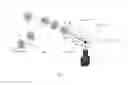
FIG. 1 is a perspective view of a robot system according to an embodiment.
DETAILED DESCRIPTION OF THE EMBODIMENT(S)
Exemplary embodiments of the present invention will be described hereinafter in detail with reference to the attached drawings, wherein like reference numerals refer to like elements. The present invention may, however, be embodied in many different forms and should not be construed as being limited to the embodiments set forth herein. Rather, these embodiments are provided so that the present disclosure will be thorough and complete and will fully convey the concept of the disclosure to those skilled in the art.
A robot system according to an embodiment is shown in FIG. 1. In the shown embodiment, the robot system is a 6-axis robot system. In other embodiments, the robot system may be any multi-freedom robot system, for example, a four-axis robot system or a five-axis robot system. The robot system has a vision sensor 10, a robot 20 having a flange 21, and an end execution tool 30 mounted on the flange 21 of the robot 20.
In order to calibrate the robot system, as shown in FIG. 1, a ball-rod member 41, 42 is fixed to the end execution tool 30. The ball-rod member 41, 42 has a connection rod 41 and a sphere 42 connected to a first end of the connection rod 41. An opposite second end of the connection rod 41 is fixed to the end execution tool 30 mounted on the flange 21 of the robot 20. As shown in FIG. 1, a center axis of the connection rod 41 passes through the center of the sphere 42.
Geometric parameters of the connection rod 41 and the sphere 42 of the ball-rod member 41, 42 are known and constant. After the ball-rod member 41, 42 is fixed to the end execution tool 30, a transformation matrix Tc of the center Tool of the end execution tool 30 with respect to the center of the sphere 42 may be pre-obtained. Since the geometry parameters of the connection rod 41 and the sphere 42 of the ball-rod member are known and constant, the transformation matrix Tc also is known and constant.
In an embodiment, the vision sensor 10 is a camera. The camera 10 is configured to capture an image of the sphere 42 of the ball-rod member 41, 42. The camera 10 identifies an actual position of the center of the sphere 42, for example, in a vision sensor coordinate system or in a world coordinate system. In another embodiment, the vision sensor 10 is a plurality of cameras.
The robot system further comprises a controller configured to control the robot system based on a program stored in a non-transitory computer readable medium, and a processor configured to process the image data obtained by the camera 10 such that the actual position of the center of the sphere 42 may be identified.
A calibration process of the robot system will now be described with reference to FIG. 1. The calibration process comprises the steps of:
-
- providing the ball-rod member 41, 42 comprising the connection rod 41 and the sphere 42 connected to the first end of the connection rod 41;
- fixing the second end of the connection rod 41 to the end execution tool 30 mounted on the flange 21 of the robot 20;
- controlling the robot 20 to move a center of the sphere 42 to the same one target point in a plurality of different poses under the guidance of the vision sensor 10. The plurality of different poses including a pose1, a pose2, a pose3, and a pose4 in the shown embodiment;
- calculating a transformation matrix Ts of the center of the sphere 42 with respect to a center Tool0 of the flange 21 based on pose data of the robot 20 at the same target point; and
calculating a transformation matrix Tt of a center Tool of the end execution tool 30 with respect to the center Tool0 of the flange 21 according to a following formula (1):
Tt=Ts * Tc (1)
The transformation matrix Tc is a transformation matrix of the center Tool of the end execution tool 30 with respect to the center of the sphere 42, and the transformation matrix Tc is known and constant.
In the controlling step, based on a position error between an actual position of the center of the sphere 42 in a vision sensor coordinate system, sensed by the vision sensor 10, and a position of the target point in the vision sensor coordinate system, a closed-loop feedback control on the robot 20 is performed until the position error becomes zero. The closed-loop feedback control is performed on the robot 20 until the center of the sphere 42 is accurately moved to the target point.
The vision sensor 10 directly identifies the actual position of the center of the sphere 42 in the vision sensor coordinate system. The actual position of the center of the sphere 42 in the world coordinate system is indicated by X, Y, and Z values, however, the actual position of the center of the sphere 42 in the vision sensor coordinate system is indicated by U, V, and Z values, in which U and V indicate positions of pixel points, and Z indicates a diameter of the sphere 42. Thereby, in the vision sensor coordinate system, the Z value is increased with the increased diameter of the sphere 42 and decreased with the decreased diameter of the sphere 42.
The controlling step thereby includes the steps of:
-
- controlling the robot 20 to move the center of the sphere 42 to the target point within a view field of the vision sensor 10 in a first pose pose1 under the guidance of the vision sensor 10, and obtaining a first pose data of the robot 20 at the target point;
- controlling the robot 20 to move the center of the sphere 42 to the target point in a second pose pose2 under the guidance of the vision sensor 10, and obtaining a second pose data of the robot 20 at the target point;
- controlling the robot 20 to move the center of the sphere 42 to the target point in a third pose3 under the guidance of the vision sensor 10, and obtaining a third pose data of the robot 20 at the target point;
- controlling the robot 20 to move the center of the sphere 42 to the target point in a fourth pose pose4 under the guidance of the vision sensor 10, and obtaining a fourth pose data of the robot 20 at the target point; and
- calculating the transformation matrix Ts of the center of the sphere 42 with respect to the center Tool0 of the flange 21 based on the obtained first pose data, second pose data, third pose data and fourth pose data of the robot 20.
In other embodiments, the robot 20 may accurately move the center of the sphere 42 to the same one target point in two, three, five or more different poses.
Advantageously, since the ball-rod member 41, 42 is mounted to the flange 21 of the robot 20, only the center of the sphere 42 of the ball-rod member 41, 42 needs to be identified by the vision sensor 10. The center of the end execution tool 30 does not need to be directly identified by the vision sensor 10. Since the sphere 42 has a regular geometry, it is easy to identify its center, which improves the calibration accuracy and efficiency of the robot system.
Claims
What is claimed is:1. An automatic calibration method for a robot system, comprising:
providing a ball-rod member including a connection rod and a sphere connected to a first end of the connection rod;
fixing an opposite second end of the connection rod to an end execution tool mounted on a flange of a robot;
controlling the robot to move a center of the sphere to a same target point in a plurality of different poses under the guidance of a vision sensor;
calculating a transformation matrix Ts of the center of the sphere with respect to a center of the flange based on pose data of the robot at the same target point; and
calculating a transformation matrix Tt of a center of the end execution tool with respect to the center of the flange according to a following formula:
Tt=Ts * Tc,
wherein Tc is a transformation matrix of the center of the end execution tool with respect to the center of the sphere and is constant.
2. The method of claim 1, wherein the controlling step includes performing a closed-loop feedback control on the robot until a position error between an actual position of the center of the sphere sensed by the vision sensor in a vision sensor coordinate system and a position of the same target point in the vision sensor coordinate system becomes zero.
3. The method of claim 2, wherein the vision sensor is at least one camera and is configured to identify the center of the sphere according to an image of the sphere captured by the at least one camera.
4. The method of claim 3, wherein the controlling step includes controlling the robot to move the center of the sphere to the same target point in at least three different poses.
5. The method of claim 3, wherein the controlling step includes:
controlling the robot to move the center of the sphere to the same target point within a view field of the vision sensor in a first pose under the guidance of the vision sensor and obtaining a first pose data of the robot at the same target point;
controlling the robot to move the center of the sphere to the same target point in a second pose under the guidance of the vision sensor and obtaining a second pose data of the robot at the same target point;
controlling the robot to move the center of the sphere to the same target point in a third pose under the guidance of the vision sensor and obtaining a third pose data of the robot at the same target point;
controlling the robot to move the center of the sphere to the same target point in a fourth pose under the guidance of the vision sensor and obtaining a fourth pose data of the robot at the same target point; and
calculating the transformation matrix Ts of the center of the sphere with respect to the center of the flange based on the obtained first pose data, second pose data, third pose data and fourth pose data of the robot.
6. The method of claim 1, wherein the robot is a multi-axis robot.
7. The method of claim 6, wherein the robot is a four-axis robot or a six-axis robot.
Images & Drawings included:

Sources:
- United States Patent and Trademark Office - verify current appl. status at the USPTO↗
Similar patent applications:
- » 20160346932
Automatic calibration method for robot systems using a vision sensor - » 20190022867
Automatic calibration method for robot system - » 20220379483
Automatic calibration method and device for robot vision system - » 16505466
Method and system for performing automatic camera calibration for robot control - » 16456074
Method and system for performing automatic camera calibration for robot control - » 16362471
Method and system for performing automatic camera calibration for robot control - » 20220172399
METHOD AND SYSTEM FOR PERFORMING AUTOMATIC CAMERA CALIBRATION FOR ROBOT CONTROL - » 16295940
Method and system for performing automatic camera calibration for robot control - » 20200238525
System and method for automatic hand-eye calibration of vision system for robot motion
Recent applications in this class:
- » 20250289138 2025-09-18
ROBOT, METHOD FOR CONTROLLING ROBOT, AND NON-TRANSITORY COMPUTER-READABLE STORAGE MEDIUM STORING COMPUTER PROGRAM FOR CONTROLLING ROBOT - » 20250262768 2025-08-21
METHOD FOR CALIBRATING A ROBOT - » 20250256403 2025-08-14
SYSTEMS AND METHODS FOR CONFIGURING A ROBOT TO INTERFACE WITH EQUIPMENT - » 20250236020 2025-07-24
AUTOMATIC ROBOT CALIBRATION FOR MULTI-JOINT ROBOTS - » 20250229430 2025-07-17
CALIBRATION APPARATUS AND CONVEYANCE ROBOT INCLUDING THE SAME - » 20250229429 2025-07-17
METHOD TO CALIBRATE A ROBOT TO A PALLET OR AN INFEED CONVEYOR - » 20250229428 2025-07-17
COORDINATE SYSTEM CALIBRATION METHOD, APPARATUS AND SYSTEM FOR ROBOT, AND MEDIUM - » 20250214247 2025-07-03
Iterative Robot-Vision Calibration - » 20250214246 2025-07-03
METHOD AND SYSTEM FOR CONTROLLING AN ARTWORK-GENERATING ROBOT USING A ROBOT INTERFACE SYSTEM - » 20250214245 2025-07-03
SUBSTRATE TRANSFER APPARATUS AND METHOD OF CALIBRATING SUBSTRATE TRANSFER APPARATUS
Recent applications for this Assignee:
- » 20250289175 2025-09-18
Tool Conveying Device and Heat Shrink Equipment - » 20250289135 2025-09-18
Robot System - » 20250279219 2025-09-04
Wire - » 20250273937 2025-08-28
Cable Aluminum Foil Layer Processing Device and Method - » 20250273366 2025-08-28
CABLE BRAIDED LAYER PROCESSING DEVICE AND METHOD - » 20250262785 2025-08-21
Terminal Strip Cutting System and Terminal Strip Cutting Method - » 20250253597 2025-08-07
Connector Housing Assembly and Connector - » 20250253577 2025-08-07
Connector and Cap - » 20250253576 2025-08-07
Connector Housing Assembly, Connector and Connector Assembly - » 20250253572 2025-08-07
Terminal, Connector and Connector Assembly