REEL COMPARTMENT COVER
US20260145904A1
2026-05-28
19/401,274
2025-11-25
Smart Summary: A reel compartment cover is designed to stop objects from getting stuck inside. It has multiple connected surfaces that are arranged in a way that allows them to move apart when something is pushed through the center opening. These surfaces are made from a flexible material that goes back to its original shape once the object is taken out. The cover has a larger circular or semicircular opening that matches the size of the object. This design helps keep the compartment clear while still allowing easy access. 🚀 TL;DR
Abstract:
A reel compartment cover for preventing trapping of an object includes a plurality of offset, vertically interconnected surfaces with a center opening positioned above and below each other in a larger circular or semicircular opening; wherein the interconnected surfaces spread apart when the object is inserted through the center opening; wherein the interconnected surfaces are constructed from a flexible material that returns to original shape when the object passes through or is removed from the center opening; and wherein the opening formed by the interconnected surfaces is as large as the diameter of the circular or semicircular opening.
Inventors:
- Venkata R. Penumatcha 19 🇺🇸 Plano, TX, United States
- Nicolas P. Guiffault 6 🇺🇸 Allen, TX, United States
- Larry D. Hall 4 🇺🇸 Richardson, TX, United States
Assignee:
- Optical Cable Corporation 42 🇺🇸 Roanoke, VA, United States
Applicant:
Interested in similar patents?
Get notified when new applications in this technology area are published.
Classification:
B65H75/4402 » CPC main
Storing webs, tapes, or filamentary material, e.g. on reels; Cores, formers, supports, or holders for coiled, wound, or folded material, e.g. reels, spindles, bobbins, cop tubes, cans, mandrels or chucks specially adapted or mounted for storing and repeatedly paying-out and re-storing lengths of material provided for particular purposes, e.g. anchored hoses, power cables involving the use of a core or former internal to, and supporting, a stored package of material; Constructional details Guiding arrangements to control paying-out and re-storing of the material
B65H75/4471 » CPC further
Storing webs, tapes, or filamentary material, e.g. on reels; Cores, formers, supports, or holders for coiled, wound, or folded material, e.g. reels, spindles, bobbins, cop tubes, cans, mandrels or chucks specially adapted or mounted for storing and repeatedly paying-out and re-storing lengths of material provided for particular purposes, e.g. anchored hoses, power cables involving the use of a core or former internal to, and supporting, a stored package of material; Constructional details; Arrangements of the frame or housing Housing enclosing the reel
B65H2601/261 » CPC further
Problem to be solved or advantage achieved; Avoiding or preventing undesirable effects; Damages to handling machine Clogging
B65H75/44 IPC
Storing webs, tapes, or filamentary material, e.g. on reels; Cores, formers, supports, or holders for coiled, wound, or folded material, e.g. reels, spindles, bobbins, cop tubes, cans, mandrels or chucks specially adapted or mounted for storing and repeatedly paying-out and re-storing lengths of material provided for particular purposes, e.g. anchored hoses, power cables involving the use of a core or former internal to, and supporting, a stored package of material Constructional details
Description
CROSS REFERENCE TO RELATED APPLICATIONS
The present application claims the priority of U.S. Provisional Patent Application Ser. No. 63/724,477 filed Nov. 25, 2024, entitled “CABLE REEL FEATURES”, which is incorporated herein in its entirety.
BACKGROUND
Cable reels, also known as drums or spools, are cylindrical devices essential for the organized storage, transport, and dispensing of various types of electrical wires, fiber optic cables, and wire ropes. These reels are utilized across a wide range of industries, such as telecommunications, construction, entertainment and mining, to prevent tangling and ensure efficient deployment. Depending on the application and load requirements, they are constructed from diverse materials; for instance, heavy-duty steel reels are often used for industrial mining operations, while lighter plastic or plywood reels are common for commercial wiring or disposable applications. Advanced models may even include features such as spring-loaded retraction, motorized winding, or “live” connections that allow the cable to be used while still spooled.
Cable reel systems require protective compartment covers for their openings to prevent contamination and damage while allowing access for cables and other objects. Previous cover designs have suffered from a significant drawback in that they would trap objects that did not fully penetrate the cover opening. This creates operational difficulties and potential damage to both the inserted objects and the cover system itself. Previous attempts to address problems associated with reel compartment covers have not adequately addressed the problem of object trapping while maintaining effective sealing of the reel compartment.
BRIEF DESCRIPTION OF THE DRAWING
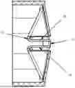
FIG. 1 is a front elevation view of a reel compartment cover;
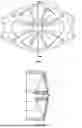
FIG. 2 is a cross-section view taken along line 2-2 in FIG. 1; and
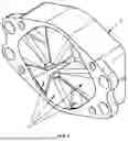
FIG. 3 is a front elevation view of the reel compartment cover.
DETAILED DESCRIPTION
As discussed herein, a reel compartment cover 10 that does not trap objects inserted into the center opening is provided.
As shown in FIGS. 1-3, the reel compartment cover 10 includes multiple offset, vertically interconnected surfaces 12 with a center opening 14 positioned above and below each other in a larger circular or semicircular opening 20 that spread apart when an object is inserted in its center. The interconnected surfaces 12 form an opening 14 that is as large as the diameter of the circular or semicircular opening, and these surfaces 12 are made of a flexible material that returns to their original shape when the inserted object passes through or is removed from the center opening 14.
The multiple, offset, vertically interconnected surfaces 12 may consist of multiple number of offset parts 16 and be of different heights relative to each other. The vertical surfaces 18 may be perpendicular, sloped or angled between the offset parts 16. The center opening 14 may be centered or offset and the exterior shape 20 formed by the offset surfaces can be but is not limited to circular.
The flexible material used in construction of the reel compartment cover 10 can be any suitable flexible material including, but not limited to, rubber, allowing the cover to flex to create a wide opening. The flexible material enables the surfaces to return to their original shape when the inserted object passes through or is removed from the center opening 14.
The interconnected surfaces 12 are configured such that the opening 14 formed is as large as the diameter of the circular or semicircular opening 20 when an object is inserted. This design ensures that objects do not become trapped during insertion or removal, addressing a key problem associated with reel compartment covers.
The reel compartment cover 10 is designed for fitment and manufacturability, allowing for practical implementation in cable reel systems. The design facilitates easy opening and closing while maintaining protective coverage of the cable reel opening.
As described herein, a reel compartment cover 10 for preventing trapping of an object includes:
-
- a plurality of offset, vertically interconnected surfaces 12 with a center opening 14 positioned above and below each other in a larger circular or semicircular opening 20;
- wherein the interconnected surfaces 12 spread apart when the object is inserted through the center opening 14;
- wherein the interconnected surfaces 12 are constructed from a flexible material that returns to original shape when the object passes through or is removed from the center opening 14; and
- wherein the opening 14 formed by the interconnected surfaces 12 is as large as the diameter of the circular or semicircular opening 20.
The figures and descriptions provided herein may have been simplified to illustrate aspects that are relevant for a clear understanding of the herein described devices, systems, and methods, while eliminating, for the purpose of clarity, other aspects that may be found in typical devices, systems, and methods. Those of ordinary skill may recognize that other elements and/or operations may be desirable and/or necessary to implement the devices, systems, and methods described herein. Because such elements and operations may be well known in the art, and because they do not facilitate a better understanding of the present disclosure, a discussion of such elements and operations is not provided herein. The present disclosure is deemed to inherently include all such elements, variations, and modifications to the described aspects that would be known to those of ordinary skill in the art, particularly in view of reading the present disclosure. Any headings used herein are for organizational purposes only and are not meant to be used to limit the scope of the description or the claims.
The terminology used herein is for the purpose of describing particular example embodiments or implementations only and is not intended to be limiting. As used herein, the singular forms “a”, “an”, and “the” may be intended to include the plural forms as well, unless the context clearly indicates otherwise.
The terms “comprises,” “comprising,” “includes,” “including,” “has,” “having,” and variations in form thereof are inclusive or variations in form thereof are intended to be inclusive in a manner similar to the term “comprises” as that term is interpreted when employed as a transitional word in a claim, and therefore specify the presence of stated features, integers, steps, operations, elements, and/or components, but do not preclude the presence or addition of one or more other features, integers, steps, operations, elements, components, and/or groups thereof unless explicitly stated otherwise or the context clearly requires otherwise.
The method steps, processes, and operations described herein are not to be construed as necessarily requiring their performance in the particular order discussed or illustrated, unless specifically identified as an order of performance. It is also to be understood that additional or alternative steps may be employed.
When an element or layer is referred to as being “on”, “engaged to”, “connected to” or “coupled to” another element or layer, it may be directly on, engaged, connected or coupled to the other element or layer, or intervening elements or layers may be present. In contrast, when an element is referred to as being “directly on,” “directly engaged to”, “directly connected to” or “directly coupled to” another element or layer, there may be no intervening elements or layers present. Other words used to describe the relationship between elements should be interpreted in a like fashion (e.g., “between” versus “directly between,” “adjacent” versus “directly adjacent,” etc.). As used herein, the term “and/or” includes any and all combinations of one or more of the associated listed items.
Although the terms first, second, third, etc., may be used herein to describe various elements, components, regions, layers and/or sections, these elements, components, regions, layers and/or sections should not be limited by these terms. These terms may be only used to distinguish one element, component, region, layer or section from another element, component, region, layer or section. Terms such as “first,” “second,” and other numerical terms when used herein do not imply a sequence or order unless clearly indicated by the context. Thus, a first element, component, region, layer or section discussed below could be termed a second element, component, region, layer or section without departing from the teachings of the exemplary embodiments and implementations.
Unless otherwise defined, all terms (including technical and scientific terms) used herein have the same meaning as commonly understood by one of ordinary skill in the art to which this subject matter belongs. It will be further understood that terms, such as those defined in commonly used dictionaries, should be interpreted as having a meaning that is consistent with their meaning in the context of the specification and relevant art and should not be interpreted in an idealized or overly formal sense unless expressly so defined herein. For brevity and/or clarity, well-known functions or constructions may not be described in detail herein.
The terms “for example” and “such as” mean “by way of example and not of limitation.” The subject matter described herein is provided by way of illustration for the purposes of teaching, suggesting, and describing, and not limiting or restricting. Combinations and alternatives to the illustrated embodiments and implementations are contemplated, described herein, and set forth in the claims.
The term “exemplary” is used herein to mean serving as an example, instance, or illustration. Any aspect or design described herein as “exemplary” is not necessarily to be construed as preferred or advantageous over other aspects or designs. Similarly, examples are provided herein solely for purposes of clarity and understanding and are not meant to limit the subject innovation or portion thereof in any manner.
For convenience of discussion herein, when there is more than one of a component, that component may be referred to herein either collectively or singularly by the singular reference numeral unless expressly stated otherwise or the context clearly indicates otherwise. For example, components N (plural) or component N (singular) may be used unless a specific component is intended. Also, the singular forms “a,” “an,” and “the” are intended to include the plural forms as well, unless expressly stated otherwise or the context indicates otherwise.
The terms “includes,” “has,” “having,” or “exhibits,” or variations in form thereof are intended to be inclusive in a manner similar to the term “comprises” as that term is interpreted when employed as a transitional word in a claim.
It will be understood that when a component is referred to as being “connected” or “coupled” to another component, it can be directly connected or coupled or coupled by one or more intervening components unless expressly stated otherwise or the context clearly indicates otherwise.
The term “and/or” includes any and all combinations of one or more of the associated listed items.
As used herein, phrases such as “between X and Y” and “between about X and Y” should be interpreted to include X and Y unless expressly stated otherwise or the context clearly indicates otherwise.
Terms such as “about”, “approximately”, “around”, and “substantially” are relative terms and indicate that, although two values may not be identical, their difference is such that the apparatus or method still provides the indicated or desired result, or that the operation of a device or method is not adversely affected to the point where it cannot perform its intended purpose. As an example, and not as a limitation, if a height of “approximately X inches” is recited, a lower or higher height is still “approximately X inches” if the desired function can still be performed or the desired result can still be achieved.
While terms such as vertical, horizontal, upper, lower, bottom, top, and the like may be used herein, it is to be understood that these terms are used for ease in referencing the drawing and, unless otherwise indicated or required by context, does not denote a required orientation.
The different advantages and benefits disclosed and/or provided by the implementation(s) disclosed herein may be used individually or in combination with one, some or possibly even all of the other benefits. Furthermore, not every implementation, nor every component of an implementation, is necessarily required to obtain, or necessarily required to provide, one or more of the advantages and benefits of the implementation.
Conditional language, such as, among others, “can”, “could”, “might”, or “may”, unless specifically stated otherwise, or otherwise understood within the context as used, is generally intended to convey that certain embodiments and implementations preferably or optionally include certain features, elements and/or steps, while some other embodiments and implementations optionally do not include those certain features, elements and/or steps. Thus, such conditional language indicates, in general, that those features, elements and/or steps are used in a permissive sense rather than a mandatory sense, and may not be required for every implementation or embodiment.
The subject matter described herein is provided by way of illustration only and should not be construed as limiting the nature and scope of the claims herein. While different embodiments and implementations have been provided above, it is not possible to describe every conceivable combination of components or methodologies for implementing the disclosed subject matter, and one of ordinary skill in the art may recognize that further combinations and permutations that are possible. Furthermore, the nature and scope of the claims is not necessarily limited to implementations that solve any or all disadvantages which may have been noted in any part of this disclosure. Various modifications and changes may be made to the subject matter described herein without departing from the spirit and scope of, the exemplary embodiments, implementations, and applications illustrated and described herein.
Although the subject matter presented herein has been described in language specific to components used therein, it is to be understood that the scope of the claims is not necessarily limited to the specific components or characteristics thereof described herein; rather, the specific components and characteristics thereof are disclosed as example forms of implementing the disclosed subject matter. Accordingly, the disclosed subject matter is intended to embrace all alterations, modifications, and variations, that fall within the scope and spirit of any claims included herein or that may be written.
The foregoing description and figures are intended only to convey to a person having ordinary skill in the art the fundamental aspects of the disclosed subject matter and are not intended to limit, and should not be construed as limiting, the scope of any present or future claims. Further, in the foregoing Detailed Description, various features may be grouped together in a single embodiment or implementation for the purpose of streamlining the disclosure. This method of disclosure is not to be interpreted as reflecting an intention that a claimed embodiment, implementation, or application requires more features than are expressly recited in a present or future claim. Rather, present and future claims reflect patentable subject matter which may lie in less than all features of a single disclosed embodiment, implementation, or application.
Claims
1. A reel compartment cover for preventing trapping of an object comprising:
a plurality of offset, vertically interconnected surfaces with a center opening positioned above and below each other in a larger circular or semicircular opening;
wherein the interconnected surfaces spread apart when the object is inserted through the center opening;
wherein the interconnected surfaces are constructed from a flexible material that returns to original shape when the object passes through or is removed from the center opening; and
wherein the opening formed by the interconnected surfaces is as large as the diameter of the circular or semicircular opening.
2. The reel compartment cover of claim 1, wherein said flexible material comprises rubber.
3. The reel compartment cover of claim 1, wherein said multiple, offset, vertically interconnected surfaces comprise multiple offset parts of different heights from each other.
4. The reel compartment cover of claim 1, wherein said vertically interconnected surfaces are selected from the group consisting of perpendicular, sloped, and angled surfaces between said offset parts.
5. The reel compartment cover of claim 1, wherein said center opening is positioned in an offset configuration.
6. The reel compartment cover of claim 1, wherein said outside shape of said offset surfaces is circular.
7. The reel compartment cover of claim 1, wherein said cover does not trap objects inserted into said center opening.
8. The reel compartment cover of claim 1, wherein said cover provides fully opening capability for inserted objects.
Images & Drawings included:
Sources:
- United States Patent and Trademark Office - verify current appl. status at the USPTO↗
Recent applications in this class:
- » 20260008649 2026-01-08
HOSE REEL - » 20250236486 2025-07-24
DEVICE FOR COVERING A SURFACE COMPRISING A DRUM LONGITUDINAL TRANSLATION MECHANISM, PROVIDED WITH A CLUTCH SYSTEM - » 20250187868 2025-06-12
CABLE REEL ASSEMBLY - » 20240400347 2024-12-05
DRILL TRAIL CABLE MANAGEMENT SYSTEM - » 20240025697 2024-01-25
WINDING UNIT FOR A CABLE - » 20230382682 2023-11-30
Rapid Rewinding Tool for Small Spools - » 20230029952 2023-02-02
SYSTEM FOR AUTOMATED CHARGING MANAGEMENT - » 20220234863 2022-07-28
Mechanism for winding cord - » 20210347601 2021-11-11
REEL DEVICE FOR CHARGING CABLE - » 20210122605 2021-04-29
Hose reel unit and hose reel assembly comprising a hose reel unit
Recent applications for this Assignee:
- » 20260145908 2026-05-28
MULTI-DIRECTION FOLDABLE REEL HANDLE - » 20260145902 2026-05-28
EXTERNAL DRIVE FEATURE FOR A CABLE REEL - » 20260145900 2026-05-28
CABLE REEL WITH COMPARTMENT HUB FEATURE - » 20260016650 2026-01-15
MULTICORE FIBER STRANDS FOR FIBER OPTIC COMMUNICATION - » 20210231898 2021-07-29
Splice sleeve holder nest - » 20210226377 2021-07-22
Bidirectionally installable intermediate modular adapter for a rack-mounted panel - » 20200280151 2020-09-03
Bidirectionally installable intermediate modular adapter for a rack-mounted panel - » 20200106252 2020-04-02
Structures for securing broadcast cabling and connectors - » 20190305496 2019-10-03
Multi-stage termination of a cable to an RJ-45 outlet - » 20190273347 2019-09-05
Plated Modular Adapter