Semiconductor package with embedded die and its methods of fabrication
US20110215464A1
2011-09-08
12/655,335
2009-12-29
✅ Patent granted
US 8,901,724 B2
2014-12-02
-
-
Teresa M Arroyo
Winkle, PLLC
2030-07-10
Abstract:
Embodiments of the present invention describe a semiconductor package having an embedded die. The semiconductor package comprises a coreless substrate that contains the embedded die. The semiconductor package provides die stacking or package stacking capabilities. Furthermore, embodiments of the present invention describe a method of fabricating the semiconductor package that minimizes assembly costs.
Inventors:
- Ravi K. Nalla 15 🇺🇸 Chandler, AZ, United States
- Javier Soto Gonzalez 41 🇺🇸 Chandler, AZ, United States
- Nicholas R. Watts 20 🇺🇸 Phoenix, AZ, United States
- John Stephen Guzek 2 🇺🇸 Chandler, AZ, United States
Assignee:
- INTEL CORPORATION 47,158 🇺🇸 Santa Clara, CA, United States
Applicant:
Interested in similar patents?
Get notified when new applications in this technology area are published.
Classification:
H01L23/538 IPC
Details of semiconductor or other solid state devices; Arrangements for conducting electric current within the device in operation from one component to another, i.e. interconnections, e.g. wires, lead frames the interconnection structure between a plurality of semiconductor chips being formed on, or in, insulating substrates
H01L24/11 » CPC main
Arrangements for connecting or disconnecting semiconductor or solid-state bodies; Methods or apparatus related thereto; Means for bonding being attached to, or being formed on, the surface to be connected, e.g. chip-to-package, die-attach, "first-level" interconnects; Manufacturing methods related thereto; Bump connectors ; Manufacturing methods related thereto Manufacturing methods
H01L21/768 » CPC further
Processes or apparatus adapted for the manufacture or treatment of semiconductor or solid state devices or of parts thereof; Manufacture or treatment of devices consisting of a plurality of solid state components formed in or on a common substrate or of parts thereof; Manufacture of integrated circuit devices or of parts thereof; Manufacture of specific parts of devices defined in group Applying interconnections to be used for carrying current between separate components within a device comprising conductors and dielectrics
H01L24/19 » CPC further
Arrangements for connecting or disconnecting semiconductor or solid-state bodies; Methods or apparatus related thereto; Means for bonding being attached to, or being formed on, the surface to be connected, e.g. chip-to-package, die-attach, "first-level" interconnects; Manufacturing methods related thereto; High density interconnect [HDI] connectors; Manufacturing methods related thereto Manufacturing methods of high density interconnect preforms
H01L24/27 » CPC further
Arrangements for connecting or disconnecting semiconductor or solid-state bodies; Methods or apparatus related thereto; Means for bonding being attached to, or being formed on, the surface to be connected, e.g. chip-to-package, die-attach, "first-level" interconnects; Manufacturing methods related thereto; Layer connectors, e.g. plate connectors, solder or adhesive layers; Manufacturing methods related thereto Manufacturing methods
H01L24/83 » CPC further
Arrangements for connecting or disconnecting semiconductor or solid-state bodies; Methods or apparatus related thereto; Methods for connecting semiconductor or other solid state bodies using means for bonding being attached to, or being formed on, the surface to be connected using a layer connector
H01L23/315 » CPC further
Details of semiconductor or other solid state devices; Encapsulations, e.g. encapsulating layers, coatings, e.g. for protection characterised by the arrangement or shape the device being completely enclosed the encapsulation having a cavity
H01L24/26 » CPC further
Arrangements for connecting or disconnecting semiconductor or solid-state bodies; Methods or apparatus related thereto; Means for bonding being attached to, or being formed on, the surface to be connected, e.g. chip-to-package, die-attach, "first-level" interconnects; Manufacturing methods related thereto Layer connectors, e.g. plate connectors, solder or adhesive layers; Manufacturing methods related thereto
H01L24/73 » CPC further
Arrangements for connecting or disconnecting semiconductor or solid-state bodies; Methods or apparatus related thereto Means for bonding being of different types provided for in two or more of groups , , , , , , ,
H01L25/074 » CPC further
Assemblies consisting of a plurality of individual semiconductor or other solid state devices ; Multistep manufacturing processes thereof all the devices being of a type provided for in the same subgroup of groups - , e.g. assemblies of rectifier diodes the devices not having separate containers the devices being of a type provided for in group Stacked arrangements of non-apertured devices
H01L25/117 » CPC further
Assemblies consisting of a plurality of individual semiconductor or other solid state devices ; Multistep manufacturing processes thereof all the devices being of a type provided for in the same subgroup of groups - , e.g. assemblies of rectifier diodes the devices having separate containers the devices being of a type provided for in group Stacked arrangements of devices
H01L2224/03462 » CPC further
Indexing scheme for arrangements for connecting or disconnecting semiconductor or solid-state bodies and methods related thereto as covered by; Means for bonding being attached to, or being formed on, the surface to be connected, e.g. chip-to-package, die-attach, "first-level" interconnects; Manufacturing methods related thereto; Bonding areas; Manufacturing methods related thereto; Manufacturing methods by blanket deposition of the material of the bonding area; Plating Electroplating
H01L2224/0401 » CPC further
Indexing scheme for arrangements for connecting or disconnecting semiconductor or solid-state bodies and methods related thereto as covered by; Means for bonding being attached to, or being formed on, the surface to be connected, e.g. chip-to-package, die-attach, "first-level" interconnects; Manufacturing methods related thereto; Bonding areas; Manufacturing methods related thereto; Structure, shape, material or disposition of the bonding areas prior to the connecting process Bonding areas specifically adapted for bump connectors, e.g. under bump metallisation [UBM]
H01L2224/11831 » CPC further
Indexing scheme for arrangements for connecting or disconnecting semiconductor or solid-state bodies and methods related thereto as covered by; Means for bonding being attached to, or being formed on, the surface to be connected, e.g. chip-to-package, die-attach, "first-level" interconnects; Manufacturing methods related thereto; Bump connectors; Manufacturing methods related thereto; Manufacturing methods; Post-treatment of the bump connector; Reworking, e.g. shaping involving a chemical process, e.g. etching the bump connector
H01L2224/26 » CPC further
Indexing scheme for arrangements for connecting or disconnecting semiconductor or solid-state bodies and methods related thereto as covered by; Means for bonding being attached to, or being formed on, the surface to be connected, e.g. chip-to-package, die-attach, "first-level" interconnects; Manufacturing methods related thereto Layer connectors, e.g. plate connectors, solder or adhesive layers; Manufacturing methods related thereto
H01L2224/27312 » CPC further
Indexing scheme for arrangements for connecting or disconnecting semiconductor or solid-state bodies and methods related thereto as covered by; Means for bonding being attached to, or being formed on, the surface to be connected, e.g. chip-to-package, die-attach, "first-level" interconnects; Manufacturing methods related thereto; Layer connectors, e.g. plate connectors, solder or adhesive layers; Manufacturing methods related thereto; Manufacturing methods by local deposition of the material of the layer connector in liquid form Continuous flow, e.g. using a microsyringe, a pump, a nozzle or extrusion
H01L2224/2732 » CPC further
Indexing scheme for arrangements for connecting or disconnecting semiconductor or solid-state bodies and methods related thereto as covered by; Means for bonding being attached to, or being formed on, the surface to be connected, e.g. chip-to-package, die-attach, "first-level" interconnects; Manufacturing methods related thereto; Layer connectors, e.g. plate connectors, solder or adhesive layers; Manufacturing methods related thereto; Manufacturing methods by local deposition of the material of the layer connector in liquid form Screen printing, i.e. using a stencil
H01L2224/821 » CPC further
Indexing scheme for arrangements for connecting or disconnecting semiconductor or solid-state bodies and methods related thereto as covered by; Methods for connecting semiconductor or other solid state bodies using means for bonding being attached to, or being formed on, the surface to be connected by forming build-up interconnects at chip-level, e.g. for high density interconnects [HDI] Forming a build-up interconnect
H01L2224/83874 » CPC further
Indexing scheme for arrangements for connecting or disconnecting semiconductor or solid-state bodies and methods related thereto as covered by; Methods for connecting semiconductor or other solid state bodies using means for bonding being attached to, or being formed on, the surface to be connected using a layer connector; Bonding techniques using a polymer adhesive, e.g. an adhesive based on silicone, epoxy, polyimide, polyester; Hardening the adhesive by curing, i.e. thermosetting Ultraviolet [UV] curing
H01L2224/92132 » CPC further
Indexing scheme for arrangements for connecting or disconnecting semiconductor or solid-state bodies and methods related thereto as covered by; Methods for connecting semiconductor or solid state bodies including different methods provided for in two or more of groups - ; Specific sequence of method steps; Connecting a surface with connectors of different types; Sequential connecting processes the first connecting process involving a build-up interconnect
H01L2924/01079 » CPC further
Indexing scheme for arrangements or methods for connecting or disconnecting semiconductor or solid-state bodies as covered by; Chemical elements Gold [Au]
H01L2924/14 » CPC further
Indexing scheme for arrangements or methods for connecting or disconnecting semiconductor or solid-state bodies as covered by; Details of semiconductor or other solid state devices to be connected; Device type Integrated circuits
H01L2924/18162 » CPC further
Indexing scheme for arrangements or methods for connecting or disconnecting semiconductor or solid-state bodies as covered by; Details of package parts other than the semiconductor or other solid state devices to be connected; Encapsulation; Shape; Exposing the passive side of the semiconductor or solid-state body of a chip with build-up interconnect
H01L2924/40252 » CPC further
Indexing scheme for arrangements or methods for connecting or disconnecting semiconductor or solid-state bodies as covered by; Details of apparatuses used for either manufacturing connectors or connecting the semiconductor or solid-state body; LASER; Type being a gas CO LASER
H01L2924/40407 » CPC further
Indexing scheme for arrangements or methods for connecting or disconnecting semiconductor or solid-state bodies as covered by; Details of apparatuses used for either manufacturing connectors or connecting the semiconductor or solid-state body; LASER; Type being a solid state Yb:YAG LASER
H01L2924/40501 » CPC further
Indexing scheme for arrangements or methods for connecting or disconnecting semiconductor or solid-state bodies as covered by; Details of apparatuses used for either manufacturing connectors or connecting the semiconductor or solid-state body; LASER; Wavelength UV spectrum
H05K2201/10477 » CPC further
Indexing scheme relating to printed circuits covered by; Details of components or other objects attached to or integrated in a printed circuit board; Details of mounted components; Position of a single component Inverted
H05K2201/10477 » CPC further
Indexing scheme relating to printed circuits covered by; Details of components or other objects attached to or integrated in a printed circuit board; Details of mounted components; Position of a single component Inverted
H05K3/4682 » CPC further
Apparatus or processes for manufacturing printed circuits; Manufacturing multilayer circuits by building the multilayer layer by layer, i.e. build-up multilayer circuits Manufacture of core-less build-up multilayer circuits on a temporary carrier or on a metal foil
H05K3/4682 » CPC further
Apparatus or processes for manufacturing printed circuits; Manufacturing multilayer circuits by building the multilayer layer by layer, i.e. build-up multilayer circuits Manufacture of core-less build-up multilayer circuits on a temporary carrier or on a metal foil
H01L23/49816 » CPC further
Details of semiconductor or other solid state devices; Arrangements for conducting electric current to or from the solid state body in operation, e.g. leads, terminal arrangements ; Selection of materials therefor consisting of soldered constructions; Leads, on insulating substrates,; Additional leads joined to the metallisation on the insulating substrate, e.g. pins, bumps, wires, flat leads Spherical bumps on the substrate for external connection, e.g. ball grid arrays [BGA]
H01L21/568 » CPC further
Processes or apparatus adapted for the manufacture or treatment of semiconductor or solid state devices or of parts thereof; Manufacture or treatment of semiconductor devices or of parts thereof the devices having at least one potential-jump barrier or surface barrier, e.g. PN junction, depletion layer or carrier concentration layer; Assembly of semiconductor devices using processes or apparatus not provided for in a single one of the subgroups - , e.g. sealing of a cap to a base of a container; Encapsulations, e.g. encapsulation layers, coatings Temporary substrate used as encapsulation process aid
H01L2225/1035 » CPC further
Details relating to assemblies covered by the group but not provided for in its subgroups; All the devices being of a type provided for in the same subgroup of groups - the devices having separate containers the devices being of a type provided for in group the containers being in a stacked arrangement the lowermost container comprising a device support the device being entirely enclosed by the support, e.g. high-density interconnect [HDI]
H01L2924/01029 » CPC further
Indexing scheme for arrangements or methods for connecting or disconnecting semiconductor or solid-state bodies as covered by; Chemical elements Copper [Cu]
H01L21/6835 » CPC further
Processes or apparatus adapted for the manufacture or treatment of semiconductor or solid state devices or of parts thereof; Apparatus specially adapted for handling semiconductor or electric solid state devices during manufacture or treatment thereof; Apparatus specially adapted for handling wafers during manufacture or treatment of semiconductor or electric solid state devices or components ; Apparatus not specifically provided for elsewhere for supporting or gripping using temporarily an auxiliary support
H01L2224/73267 » CPC further
Indexing scheme for arrangements for connecting or disconnecting semiconductor or solid-state bodies and methods related thereto as covered by; Means for bonding being of different types provided for in two or more of groups; Location after the connecting process on different surfaces Layer and HDI connectors
H01L2224/12105 » CPC further
Indexing scheme for arrangements for connecting or disconnecting semiconductor or solid-state bodies and methods related thereto as covered by; Means for bonding being attached to, or being formed on, the surface to be connected, e.g. chip-to-package, die-attach, "first-level" interconnects; Manufacturing methods related thereto; Bump connectors; Manufacturing methods related thereto; Structure, shape, material or disposition of the bump connectors prior to the connecting process Bump connectors formed on an encapsulation of the semiconductor or solid-state body, e.g. bumps on chip-scale packages
H01L23/49822 » CPC further
Details of semiconductor or other solid state devices; Arrangements for conducting electric current to or from the solid state body in operation, e.g. leads, terminal arrangements ; Selection of materials therefor consisting of soldered constructions; Leads, on insulating substrates, Multilayer substrates
H05K1/185 » CPC further
Printed circuits; Printed circuits structurally associated with non-printed electric components associated with components mounted in the printed circuit board, e.g. insert mounted components [IMC] Components encapsulated in the insulating substrate of the printed circuit or incorporated in internal layers of a multilayer circuit
H01L24/48 » CPC further
Arrangements for connecting or disconnecting semiconductor or solid-state bodies; Methods or apparatus related thereto; Means for bonding being attached to, or being formed on, the surface to be connected, e.g. chip-to-package, die-attach, "first-level" interconnects; Manufacturing methods related thereto; Wire connectors; Manufacturing methods related thereto; Structure, shape, material or disposition of the wire connectors after the connecting process of an individual wire connector
H01L2924/3511 » CPC further
Indexing scheme for arrangements or methods for connecting or disconnecting semiconductor or solid-state bodies as covered by; Technical effects; Mechanical effects; Thermal stress Warping
H01L2924/01078 » CPC further
Indexing scheme for arrangements or methods for connecting or disconnecting semiconductor or solid-state bodies as covered by; Chemical elements Platinum [Pt]
H01L23/49827 » CPC further
Details of semiconductor or other solid state devices; Arrangements for conducting electric current to or from the solid state body in operation, e.g. leads, terminal arrangements ; Selection of materials therefor consisting of soldered constructions; Leads, on insulating substrates, Via connections through the substrates, e.g. pins going through the substrate, coaxial cables
H05K2203/0152 » CPC further
Indexing scheme relating to apparatus or processes for manufacturing printed circuits covered by; Tools for processing; Objects used during processing; Carriers and holders Temporary metallic carrier, e.g. for transferring material
H05K2203/0152 » CPC further
Indexing scheme relating to apparatus or processes for manufacturing printed circuits covered by; Tools for processing; Objects used during processing; Carriers and holders Temporary metallic carrier, e.g. for transferring material
H01L25/105 » CPC further
Assemblies consisting of a plurality of individual semiconductor or other solid state devices ; Multistep manufacturing processes thereof all the devices being of a type provided for in the same subgroup of groups - , e.g. assemblies of rectifier diodes the devices having separate containers the devices being of a type provided for in group
H01L2924/01033 » CPC further
Indexing scheme for arrangements or methods for connecting or disconnecting semiconductor or solid-state bodies as covered by; Chemical elements Arsenic [As]
H01L21/56 » CPC further
Processes or apparatus adapted for the manufacture or treatment of semiconductor or solid state devices or of parts thereof; Manufacture or treatment of semiconductor devices or of parts thereof the devices having at least one potential-jump barrier or surface barrier, e.g. PN junction, depletion layer or carrier concentration layer; Assembly of semiconductor devices using processes or apparatus not provided for in a single one of the subgroups - , e.g. sealing of a cap to a base of a container Encapsulations, e.g. encapsulation layers, coatings
H01L2924/00012 » CPC further
Indexing scheme for arrangements or methods for connecting or disconnecting semiconductor or solid-state bodies as covered by; Technical content checked by a classifier Relevant to the scope of the group, the symbol of which is combined with the symbol of this group
H01L2924/00014 » CPC further
Indexing scheme for arrangements or methods for connecting or disconnecting semiconductor or solid-state bodies as covered by; Technical content checked by a classifier the subject-matter covered by the group, the symbol of which is combined with the symbol of this group, being disclosed without further technical details
H01L2224/45099 » CPC further
Indexing scheme for arrangements for connecting or disconnecting semiconductor or solid-state bodies and methods related thereto as covered by; Means for bonding being attached to, or being formed on, the surface to be connected, e.g. chip-to-package, die-attach, "first-level" interconnects; Manufacturing methods related thereto; Wire connectors; Manufacturing methods related thereto; Structure, shape, material or disposition of the wire connectors prior to the connecting process of an individual wire connector; Core members of the connector Material
H01L2924/181 » CPC further
Indexing scheme for arrangements or methods for connecting or disconnecting semiconductor or solid-state bodies as covered by; Details of package parts other than the semiconductor or other solid state devices to be connected Encapsulation
H01L2924/12042 » CPC further
Indexing scheme for arrangements or methods for connecting or disconnecting semiconductor or solid-state bodies as covered by; Details of semiconductor or other solid state devices to be connected; Device type; Passive devices, e.g. 2 terminal devices; Optical Diode LASER
H01L2924/00 » CPC further
Indexing scheme for arrangements or methods for connecting or disconnecting semiconductor or solid-state bodies as covered by
H01L25/07 IPC
Assemblies consisting of a plurality of individual semiconductor or other solid state devices ; Multistep manufacturing processes thereof all the devices being of a type provided for in the same subgroup of groups - , e.g. assemblies of rectifier diodes the devices not having separate containers the devices being of a type provided for in group
H01L21/60 IPC
Processes or apparatus adapted for the manufacture or treatment of semiconductor or solid state devices or of parts thereof; Manufacture or treatment of semiconductor devices or of parts thereof the devices having at least one potential-jump barrier or surface barrier, e.g. PN junction, depletion layer or carrier concentration layer; Assembly of semiconductor devices using processes or apparatus not provided for in a single one of the subgroups - , e.g. sealing of a cap to a base of a container Attaching or detaching leads or other conductive members, to be used for carrying current to or from the device in operation
H01L2924/15311 » CPC further
Indexing scheme for arrangements or methods for connecting or disconnecting semiconductor or solid-state bodies as covered by; Details of package parts other than the semiconductor or other solid state devices to be connected; Die mounting substrate; Connection portion the connection portion being formed only on the surface of the substrate opposite to the die mounting surface being a ball array, e.g. BGA
H01L2924/1517 » CPC further
Indexing scheme for arrangements or methods for connecting or disconnecting semiconductor or solid-state bodies as covered by; Details of package parts other than the semiconductor or other solid state devices to be connected; Die mounting substrate Multilayer substrate
H01L2224/83192 » CPC further
Indexing scheme for arrangements for connecting or disconnecting semiconductor or solid-state bodies and methods related thereto as covered by; Methods for connecting semiconductor or other solid state bodies using means for bonding being attached to, or being formed on, the surface to be connected using a layer connector; Arrangement of the layer connectors prior to mounting wherein the layer connectors are disposed only on another item or body to be connected to the semiconductor or solid-state body
H01L2924/014 » CPC further
Indexing scheme for arrangements or methods for connecting or disconnecting semiconductor or solid-state bodies as covered by; Alloys Solder alloys
H01L2924/15153 » CPC further
Indexing scheme for arrangements or methods for connecting or disconnecting semiconductor or solid-state bodies as covered by; Details of package parts other than the semiconductor or other solid state devices to be connected; Die mounting substrate; Shape the die mounting substrate comprising a recess for hosting the device
H01L23/5389 » CPC main
Details of semiconductor or other solid state devices; Arrangements for conducting electric current within the device in operation from one component to another, i.e. interconnections, e.g. wires, lead frames the interconnection structure between a plurality of semiconductor chips being formed on, or in, insulating substrates the chips being integrally enclosed by the interconnect and support structures
H01L2924/01046 » CPC further
Indexing scheme for arrangements or methods for connecting or disconnecting semiconductor or solid-state bodies as covered by; Chemical elements Palladium [Pd]
H01L2221/68345 » CPC further
Processes or apparatus adapted for the manufacture or treatment of semiconductor or solid state devices or of parts thereof covered by; Apparatus for handling semiconductor or electric solid state devices during manufacture or treatment thereof; Apparatus for handling wafers during manufacture or treatment of semiconductor or electric solid state devices or components; Apparatus not specifically provided for elsewhere for supporting or gripping using temporarily an auxiliary support used as a support during the manufacture of self supporting substrates
H01L2224/73265 » CPC further
Indexing scheme for arrangements for connecting or disconnecting semiconductor or solid-state bodies and methods related thereto as covered by; Means for bonding being of different types provided for in two or more of groups; Location after the connecting process on different surfaces Layer and wire connectors
H01L23/02 IPC
Details of semiconductor or other solid state devices Containers; Seals
H01L23/12 IPC
Details of semiconductor or other solid state devices Mountings, e.g. non-detachable insulating substrates
H01L23/053 IPC
Details of semiconductor or other solid state devices; Containers; Seals characterised by the shape of the container or parts, e.g. caps, walls the container being a hollow construction and having an insulating or insulated base as a mounting for the semiconductor body
H01L23/48 IPC
Details of semiconductor or other solid state devices Arrangements for conducting electric current to or from the solid state body in operation, e.g. leads, terminal arrangements ; Selection of materials therefor
H01L23/52 IPC
Details of semiconductor or other solid state devices Arrangements for conducting electric current within the device in operation from one component to another, i.e. interconnections, e.g. wires, lead frames
H01L29/40 IPC
Semiconductor devices adapted for rectifying, amplifying, oscillating or switching, or capacitors or resistors with at least one potential-jump barrier or surface barrier, e.g. PN junction depletion layer or carrier concentration layer; Details of semiconductor bodies or of electrodes thereof; Multistep manufacturing processes therefor Electrodes ; Multistep manufacturing processes therefor
H01L23/498 IPC
Details of semiconductor or other solid state devices; Arrangements for conducting electric current to or from the solid state body in operation, e.g. leads, terminal arrangements ; Selection of materials therefor consisting of soldered constructions Leads, on insulating substrates,
H01L21/683 IPC
Processes or apparatus adapted for the manufacture or treatment of semiconductor or solid state devices or of parts thereof; Apparatus specially adapted for handling semiconductor or electric solid state devices during manufacture or treatment thereof; Apparatus specially adapted for handling wafers during manufacture or treatment of semiconductor or electric solid state devices or components ; Apparatus not specifically provided for elsewhere for supporting or gripping
H05K1/18 IPC
Printed circuits Printed circuits structurally associated with non-printed electric components
H05K1/18 IPC
Printed circuits Printed circuits structurally associated with non-printed electric components
H05K3/46 IPC
Apparatus or processes for manufacturing printed circuits Manufacturing multilayer circuits
H05K3/46 IPC
Apparatus or processes for manufacturing printed circuits Manufacturing multilayer circuits
H01L23/00 IPC
Details of semiconductor or other solid state devices
H01L2225/1058 » CPC further
Details relating to assemblies covered by the group but not provided for in its subgroups; All the devices being of a type provided for in the same subgroup of groups - the devices having separate containers the devices being of a type provided for in group the containers being in a stacked arrangement; Details of electrical connections between containers Bump or bump-like electrical connections, e.g. balls, pillars, posts
H01L25/03 » CPC further
Assemblies consisting of a plurality of individual semiconductor or other solid state devices ; Multistep manufacturing processes thereof all the devices being of a type provided for in the same subgroup of groups - , e.g. assemblies of rectifier diodes
H01L25/10 IPC
Assemblies consisting of a plurality of individual semiconductor or other solid state devices ; Multistep manufacturing processes thereof all the devices being of a type provided for in the same subgroup of groups - , e.g. assemblies of rectifier diodes the devices having separate containers
Description
BACKGROUND
1. Field
The present invention relates to the field of semiconductor packaging and more particularly to an embedded die in a semiconductor package and its method of fabrication.
2. Discussion of Related Art
Semiconductor packages are used for protecting an integrated circuit (IC) chip or die, and also to provide the die with an electrical interface to external circuitry. With the increasing demand for smaller electronic devices, semiconductor packages are designed to be even more compact and must support larger layout density. For example, some semiconductor packages now use a coreless substrate, which does not include the thick resin core layer commonly found in conventional substrates. Furthermore, the demand for higher performance devices results in a need for an improved semiconductor package that enables mixed technology die stacking or provide package stacking capability while maintaining a thin packaging profile.
BRIEF DESCRIPTION OF THE DRAWINGS
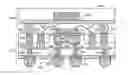
FIG. 1 is cross-sectional view that illustrates a semiconductor package in accordance with one embodiment of the present invention.
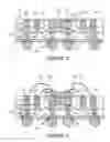
FIG. 2 is cross-sectional view that illustrates a semiconductor package in accordance with another embodiment of the present invention.
FIG. 3 is cross-sectional view that illustrates a semiconductor package in accordance with another embodiment of the present invention.
FIG. 4 is cross-sectional view that illustrates a semiconductor package in accordance with another embodiment of the present invention.
FIG. 5 is cross-sectional view that illustrates a semiconductor package in accordance with another embodiment of the present invention.
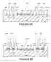
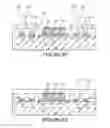
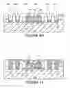
FIGS. 6A-6O are cross-sectional views that illustrate a method of fabricating the semiconductor package shown in FIG. 1.
FIGS. 7A-7E are cross-sectional views that illustrate a method of fabricating the semiconductor device shown in FIG. 5.
FIG. 8 is a system in accordance with embodiments of the present invention.
DETAILED DESCRIPTION
A semiconductor package having an embedded die and its method of fabrication are described. In the following description, numerous specific details are set forth in order to provide a thorough understanding of the present invention. In other instances, well known semiconductor processing techniques and features have not been described in particular detail in order not to unnecessarily obscure the present invention.
Embodiments of the present invention describe a semiconductor package having an embedded die. In one embodiment, the semiconductor package comprises a coreless substrate that contains the embedded die. By embedding the die in the coreless substrate, the assembly steps commonly used in conventional flip-chip assembly are eliminated, thus reducing assembly costs. Furthermore, the semiconductor package enables mixed-technology die stacking or package stacking. Hence, the semiconductor package provides the advantages of thin-profile packaging with die-stacking or package-stacking capabilities at reduced package assembly costs.
FIG. 1 illustrates a cross-sectional view of a semiconductor package 201 in accordance with one embodiment of the present invention. The semiconductor package 201 comprises a first dielectric layer 210 having a die cavity 213. In one embodiment, the die cavity 213 is centrally located and extends through the first dielectric layer 210. A layer of adhesive 220 is formed in the die cavity 213. In an embodiment of the present invention, the layer of adhesive 220 has a top surface 221 that is substantially coplanar to the top surface 211 of the first dielectric layer 210.
An integrated circuit (IC) chip or die 300 is disposed in the die cavity 213. The die 300 includes a front side 310 and a back side 320. In one embodiment, the back side 320 of the die 300 is secured or adhered to the bottom surface 222 of the layer of adhesive 220. In one embodiment, the front side 310 includes a plurality of die pads 341, 342.
A second dielectric layer 250 is formed onto the bottom surface of the first dielectric layer 210. The second dielectric layer 250 also encapsulates the die 300. In one embodiment, a plurality of die interconnects 271, 272 are formed in the second dielectric layer 250, where the die interconnects 271, 272 are electrically coupled to the die pads 341, 342 on the die 300.
In an embodiment of the present invention, a third dielectric layer 280 is formed onto the second dielectric layer 250. In one embodiment, a plurality of die interconnects 291, 292 are formed in the third dielectric layer 280. The die interconnects 291, 292 at the third dielectric layer 280 are electrically coupled to the die interconnects 271, 272 in the second dielectric layer 250.
In an embodiment of the present invention, a plurality of package pads 231, 232, 233, 234 are formed in the first dielectric layer 210. The package pads 231, 232, 233, 234 are formed at the periphery regions of the die 300. In one embodiment, each of the package pads 231, 232, 233, 234 comprises an exposed surface that is substantially coplanar with the top surface 211 of the first dielectric layer 210. Furthermore, a plurality of package interconnects 273, 274, 275, 276 are formed in the second dielectric layer 250, and are electrically coupled to the package pads 231, 232, 233, 234. In one embodiment, additional package interconnects 293, 294 are formed in the third dielectric layer 280, and are electrically coupled to the package interconnects 273, 276 in the second dielectric layer 250.
In one embodiment, die interconnects 291, 292 are formed in the third dielectric layer, where the die interconnects 291, 292 are electrically coupled to the die interconnects 271, 272.
In one embodiment, a solder resist layer 400 is formed on the third dielectric layer 280. In one embodiment, the solder resist layer 400 comprises openings that expose the die interconnects 291, 292 as well as the package interconnects 293, 294. Solder balls or bumps 411, 412, 413, 414 are formed onto the die interconnects 291, 292 and the packaged interconnects 293, 294. The solder bumps 411, 412 are electrically coupled to the die interconnects 291, 292. The solder bumps 413, 414 are electrically coupled to the package interconnects 293, 294. FIG. 1 illustrates the formation of solder bumps 411, 412, 413, 414 on the semiconductor package 201 to create a Ball Grid Array (BGA) layout. Routing or traces for the BGA layout can be formed on the solder resist layer 400. It can be appreciated that other types of layout, for example a Land Grid Array (LGA), can be formed on the semiconductor package 201.
In one embodiment, the dielectric layers 210, 250, 280 with die interconnects 271, 272, 291, 292 and package interconnects 273-276, 293, 294 constitute a coreless substrate, where the die 300 is entirely embedded in the coreless substrate. By embedding the die 300 in the coreless substrate of the semiconductor package 201, the assembly steps commonly used in conventional flip-chip assembly are eliminated, thus reducing assembly costs. In addition, the semiconductor package 201 is no longer confined to strip manufacturing capability, which enables full panel processing, further reducing manufacturing costs. Furthermore, the semiconductor package 201 enables mixed-technology die stacking or package stacking. Hence, the semiconductor package 201 provides the advantages of low-profile packaging, thin die assembly, POP compatibility, mixed-technology (e.g. wire-bond) die stacking at reduced package assembly costs.
FIG. 2 illustrates an example of die stacking on the semiconductor package 201. In one embodiment, another die 500 is attached on the semiconductor package 201. The die 500 is secured or adhered to the top surface 221 of the layer of adhesive 220. A plurality of wire-bonding interconnects 511, 512, 513, 514 electrically couple the die 500 to the package pads 231, 232, 233, 234 of the semiconductor package 201. A layer of mold compound (not shown) can be used to protect the top die and encapsulate the wirebonds. In an embodiment of the present invention, the final package shown in FIG. 2 can be attached to a printed circuit board (PCB), where the package pads 231, 232, 233, 234 and the package interconnects 273, 274, 275, 276, 293, 294 serve as electrical connections between the die 500 and the traces on the PCB.
In an embodiment of the present invention, the semiconductor package 201 with additional die 500 forms a System-in-Package (SIP) that can be used in a variety of applications, for example portable or handheld devices such as laptops or mobile phones. In a specific embodiment, the die 300 is a System-on-Chip(SOC) containing a processor module while the die 500 is a memory module for the SOC.
FIG. 3 illustrates an example of package stacking on the semiconductor package 201. In an embodiment of the present invention, another package 600 can be attached to the semiconductor package 201 to form a Package-on-Package (POP) structure. In one embodiment, the package 600 comprises a die 610 electrically coupled to a package substrate 620. A mold cap encapsulates the die 610 and serves a protection cover for the die 610. In one embodiment, a plurality of interconnects, for example solder bumps 651, 652, 653, 654, can be used to electrically couple the die 610 to the package pads 231, 232, 233, 234 of the semiconductor package 201.
In one embodiment, the POP structure shown in FIG. 3 is a System-in-Package. In a specific embodiment, the die 300 can be an SoC containing a processor module while the die 610 can be an additional logic chip for the SOC. In one embodiment, the package 600 is a flip-chip package.
In an embodiment of the present invention, the semiconductor package 201 can be used with a combination of die stacking and package stacking technologies. In one embodiment, the die 500 is attached to the top surface 221 of the layer of adhesive 220 as shown in FIG. 4. Wire-bonding interconnects 512, 513 electrically couple the die 500 to the package pads 232, 233. The package 600 is stacked over the die 500 and the semiconductor package 201. The solder bumps 651, 654 electrically couple the package 600 to the package pad 231, 234.
In an alternative embodiment, the die 300 is fully embedded in a semiconductor package without the package pads 231, 232, 233, 234 and the package interconnects 273, 274, 275, 276, 293, 294. For example, FIG. 5 illustrates an alternative semiconductor package 201′ comprising die interconnects 271, 272, 291, 292, 295, 296. Solder bumps 411, 412, 413, 414 are formed on the die interconnects 291, 292, 295, 296.
FIGS. 6A-6L illustrate a method of forming the semiconductor package 201 shown in FIG. 1. The fabrication of the semiconductor package 201 begins by providing a panel or carrier 100 as shown in FIG. 6A. In one embodiment, the carrier 100 comprises a conductive surface 110 that enables plating thereon. In a specific embodiment, the carrier 100 is made of a conductive material such as copper, and the conductive surface 110 is a copper surface. In one embodiment, the carrier 100 has a thickness of around 50 um.
Next, the first dielectric layer 210 is formed on the conductive surface 110 of the carrier 100 as shown in FIG. 6B. In one embodiment, the first dielectric layer 210 comprises a top surface 211 and bottom surface 212, where the top surface 211 is formed on the conductive surface 110. In one embodiment, the first dielectric layer 210 has about the same thickness as the die that is subsequently embedded into the first dielectric layer 210. For example, the first dielectric layer has a thickness of around 50-150 um. Then, the die cavity 213 and a plurality of pad openings 214, 215, 216, 217 are formed in the first dielectric layer 210 as shown in FIG. 6C. In one embodiment, the die cavity 213 is centrally located and extends through the first dielectric layer 210 to expose a die region 111 on the conductive surface 110. The plurality of pad openings 214, 215, 216, 217 expose a plurality of pad regions 112, 113, 114, 115 on the conductive surface 110.
In an embodiment of the present invention, the first dielectric layer 210 is made of a photo-imageable or photo-definable material. In one embodiment, the first dielectric layer 210 is made of a positive photo-definable material, where portions of the first dielectric layer 210 exposed to the radiation source are removed upon developing the first dielectric layer 210. In another embodiment, the first dielectric layer 210 is made of a negative photo-definable material, where portions of the first dielectric layer 210 exposed to the radiation source are retained upon developing the first dielectric layer 210. The photo-definable material includes but is not limited to epoxy-based photoresists. In an embodiment of the present invention, the fabrication of the (photo-definable) first dielectric layer 210 begins by laminating a layer of photo-definable material onto the conductive surface 110 (as shown in FIG. 6B). Then, the photo-definable material is exposed to a radiation source and subsequently developed to define the die cavity 211 and the plurality of pad openings 212, 213, 214, 215 (as shown in FIG. 6C).
In an alternative embodiment, the first dielectric layer 210 is made of common dielectric materials that are not photo-definable. In this case, the first dielectric layer 210 is fabricated by depositing the first dielectric layer 210 onto the conductive surface 110 (as shown in FIG. 6B), followed by defining the die cavity 211 and the pad openings 212, 213, 214, 215 in the first dielectric layer 210 (as shown in FIG. 6C). In one embodiment, the die cavity 211 and the pad openings 212, 213, 214, 215 are defined or created by common photolithography and etching processes, such as but not limited to a plasma etch process. In another embodiment, the die cavity 211 and the pad openings 212, 213, 214, 215 are defined by using laser or mechanical drilling processes commonly used in semiconductor manufacturing.
Next, the layer of adhesive 220 is formed on the die region 111 of the conductive surface 110 as shown in FIG. 6D. The layer of adhesive 220 comprises a top surface 221 and a bottom surface 222. In one embodiment, the top surface 221 is formed onto the die region 111 so that it is substantially coplanar to the top surface 211 of the first dielectric layer 210. In one embodiment, the layer of adhesive 220 is sprayed onto the die region 111. In another embodiment, the layer of adhesive 220 is formed by using a well known screen printing techniques. For example, an adhesive material is printed onto the die region 111 using a mesh mask (not shown), and then the adhesive material is cured to form the layer of adhesive 220 covering the entire die region 111. In one embodiment, the layer of adhesive 220 is selectively formed on the die region 111 only. In other words, the layer of adhesive 220 is not formed onto the pad regions 112, 113, 114, 115.
In one embodiment, the layer of adhesive 220 is formed with a thickness of around 10 to 50 um. The layer of adhesive 220 is made from materials, such as but not limited to filled epoxy-based materials. In an embodiment of the present invention, the layer of adhesive 220 remains as a permanent feature of the semiconductor package 201 to protect a die subsequently embedded in the first dielectric layer 210. Furthermore, the layer of adhesive 220 can be used as a surface for subsequent marking or used to minimize any warpage that may occur within the die.
Next, the plurality of package pads 231, 232, 233, 234 are formed on the pad regions 112, 113, 114, 115 of the conductive surface 110 as shown in FIG. 6E. In an embodiment of the present invention, the plurality of package pads 231, 232, 233, 234 are formed by using well known electrolytic plating techniques. In one embodiment, electroplating of the pad regions 112, 113, 114, 115 begins by forming a resist layer (not shown) on the first dielectric layer 210, where the resist layer is patterned to exposed the pad regions 112, 113, 114, 115. Then, the pad regions 112, 113, 114, 115 are electroplated using metals such as but not limited to gold (Au), palladium (Pd), nickel (Ni) and copper (Cu). In a specific embodiment, the pad regions 112, 113, 114, 115 are electroplated in the following order: gold, followed by palladium, followed by nickel. In this case, the plurality of package pads 231, 232, 233, 234 comprises a composition or multi-layered stack of gold, palladium and nickel. After the electroplating process is complete, the resist layer is removed from the first dielectric layer 210.
Next, the die 300 is attached to the layer of adhesive 220 as shown in FIG. 6F. The die 300 comprises a front side 310 and a back side 320. In one embodiment, the front side 310 of the die 300 includes the plurality of die pads 341, 342. In one embodiment, well known die placement techniques can be used to insert the die 300 into the die cavity 211. The die 300 is then secured or adhered to the layer of adhesive 220. In one embodiment, the back side 320 of the die 240 is adhered to the layer of adhesive 220.
FIGS. 6D and 6F describe forming the layer of adhesive 220 onto the carrier 100 prior to attaching the die 300 onto the layer of adhesive 220. In an alternative embodiment, an adhesive film is attached to the die back side 320 first before placing the die 300 with adhesive film onto the carrier 100. For example, beginning from FIG. 6C, a die 300 with the adhesive film on its back side 320 is placed onto the die region 111 of the carrier so that the adhesive film secures the die 300 onto the carrier 100. In this case, the adhesive film is only formed beneath the die 300 and does not extend beyond the edges of the die 300. In other words, the adhesive film does not cover the entire die region 111.
The layer of adhesive 220 serves as a protection layer for the die backside 320. Furthermore, the layer of adhesive 220 can be used to minimize any warpage that may occur in the die 300. In one embodiment, the layer of adhesive 220 comprises a UV-curable property that can be subsequently activated to attach a wirebond die to the top surface 221 of the layer of adhesive 220. In one embodiment, the layer of adhesive 220 comprises thermal conductive properties that facilitate heat dissipation of the die 300.
Next, a second dielectric layer 250 is formed onto the first dielectric layer 210 and the die 300 as shown in FIG. 6G. In an embodiment of the present invention, the second dielectric layer 250 is forming by well known lamination techniques. The second dielectric layer 250 can be made of materials such as but not limited to filled epoxy-based composite materials) In one embodiment, the second dielectric layer 250 is formed with a thickness of around 10-30 um.
In one embodiment, the second dielectric layer 250 encapsulates the entire die 300, including the front side 310 and sidewalls of the die 300. Furthermore, the second dielectric layer 250 is formed onto the plurality of package pads 231, 232, 233, 234. In one embodiment, the second dielectric layer 250 is formed with a level surface 251 to facilitate the subsequent build-up process.
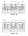
Next, a plurality of interconnects are formed on the die pads 341, 342 and the package pads 231, 232, 233, 234. In an embodiment of the present invention, a semi-additive process (SAP) is used to form the plurality of interconnects. For example, the fabrication of the plurality of interconnects begins, in FIG. 6H, by forming via openings 261, 262, 263, 264, 265, 266 in the second dielectric layer 250. In one embodiment, the via openings 261, 262 expose the die pads 341, 342 at the front side 310 of the die 300, whereas the via opening 263, 264, 265, 266 expose the package pads 231, 232, 233, 234.
In one embodiment, the via openings 261, 262, 263, 264, 265, 266 are formed by a mechanical or laser drilling process. In one embodiment, the via openings 261, 262 and the via openings 263, 264, 265, 266 are defined in separate drilling processes due to the different diameter and depth. For example, the via openings 261, 262 are formed by using a UV YAG laser source. The via openings 261, 262 are formed with a diameter size of less than 50 um. Then, the via openings 263, 264, 265, 266 are formed with a CO2 laser source. The via openings 263, 264, 265, 266 are formed with a diameter size of around 50-150 um. In an embodiment of the present invention, the surfaces of the via openings 261, 262, 263, 264, 265, 266 can be cleaned by using a desmear process based on permanganate chemistry that is commonly used in substrate manufacturing.
After forming the via openings 261, 262, 263, 264, 265, 266, a metal layer (not shown) is deposited into the via openings 261, 262, 263, 264, 265, 266, and onto the die pads 341, 342 and package pads 231, 232, 233, 234. In a specific embodiment, the metal layer starts from a copper seed layer deposited by electroless plating. Subsequently, the metal layer is patterned using well known photolithography, electrolytic copper plating, resist stripping, and etching techniques to form separate interconnects 271, 272, 273, 274, 275, 276 shown in FIG. 6I. In one embodiment, die interconnects 271, 272 are formed onto the die pads 341, 342, whereas package interconnects 273, 274, 275, 276 are formed onto the package pads 231, 232, 233, 234. The die interconnects 271, 272 and the package interconnects 273, 274, 275, 276 may be formed in separate processes.
The number of build-up layers in the semiconductor package can be increased by using the SAP build-up process. For example, repeating the steps of forming the dielectric layer, followed by forming the interconnects, thereby creating more metallization layers. For example, in FIG. 6J, a third dielectric layer 280 is formed over the second dielectric layer 250 and the interconnects 271, 272, 273, 274, 275, 276. Then, a plurality of interconnects 291, 292, 293, 294 are formed in the third dielectric layer 280. In one embodiment, the die interconnects 291, 292 are formed onto die interconnects 271, 272 such that the interconnects 291, 292 are electrically coupled to the die interconnect 271, 272. Package interconnects 293, 294 are formed over the interconnects 273, 276, where the package interconnects 293, 294 are electrically coupled to the interconnects 273, 276.
For illustrations purposes, FIG. 6J only shows two build-up layers (i.e. dielectric layers 250, 280). It can be appreciated that the number of dielectric layers or build-up layers can be increased according to the package design. In a typical design, around 3-6 build-up layers constitute the semiconductor package.
In an embodiment of the present invention, a solder resist layer 400 is formed over the uppermost dielectric layer (i.e. the third dielectric layer 280) as shown in FIG. 6K. In one embodiment, the solder resist layer 400 are formed with openings that exposes the die interconnects 291, 292 and package interconnects 293, 294. In one embodiment, the solder resist layer 400 can be screen-printed or laminated onto the third dielectric layer 280. Then, a laser process can be performed on the solder resist layer 400 to define the openings that exposes the die interconnects 291, 292 and package interconnects 293, 294. In another embodiment, the solder resist layer 400 is made of photo-definable polymer material that can be exposed to a radiation source and developed to form the openings.
Next, the carrier 100 is removed from the semiconductor package 201 to expose the package pads 231, 232, 233, 234 and the adhesive layer 220 as shown in FIG. 6L. In one embodiment, the carrier 100 is removed by using well known etching processes. In one embodiment, the etching uses an etch chemistry that is substantially selective to the first dielectric layer 210, the layer of adhesive 220, and the package pads 231, 232, 233, 234. In other words, the etch chemistry removes the carrier 100 faster than it removes the first dielectric layer 210, the layer of adhesive 220, or the package pads 231, 232, 233, 234.
Then, the solder balls or bumps 411, 412 are formed onto the exposed interconnects 292, 293. The solder bumps 411, 412 are made from well known solder materials and are formed by well known techniques, such as but not limited to evaporation, electroplating or direct placement. This completes the fabrication of the semiconductor device shown in FIG. 1. FIGS. 6A-6K shows the fabrication of the semiconductor package 201 on one side of the carrier 100. It can be appreciated that both sides of the carrier 100 can be used to form two semiconductor packages at the same time.
In another embodiment, the die 300 may be first attached to the carrier 100 (FIG. 6m). A layer 211 may be formed on the die (FIG. 6n), by a lamination process, for example. The single layer 211 may be used instead of the two layers 210 and 250 of FIG. 6I, for example, to form the structure in FIG. 6p, according to the methods described previously herein.
FIGS. 7A-7E illustrate a method of forming the semiconductor package 201′ shown in FIG. 5. The fabrication of the semiconductor package 201′ is similar to the process described in FIGS. 6A-6L except that the package interconnects are not formed in the semiconductor package 201′. Continuing from FIG. 6B, only the die cavity 213 is formed in the first dielectric layer 210 as shown in FIG. 7A. Next, the layer of adhesive 220 and the die 300 are attached over the die region 111 of the carrier 100 as shown in FIG. 7B. The methods of forming the layer of adhesive 220 and attaching the die 300 are similar to FIGS. 6D and 6F, and thus will not be described here.
Next, in FIG. 7C, the second dielectric layer 250 is formed over the first dielectric layer 210 and the die 300, followed by forming the die interconnects 271, 272 on the die pads 341, 342. The methods of forming the second dielectric layer 250 and the die interconnects 271, 272 are similar to the process described in FIGS. 6G, 6H and 61. In one embodiment, metal lines 277, 278 are formed during the fabrication of the die interconnects 271, 272. Then, the third dielectric layer 280 is formed onto the second dielectric layer 290 as shown in FIG. 7D. Die interconnects 291, 292, 295, 296 are formed in the third dielectric layer 280. In this case, the additional die interconnects 295, 296 are formed onto the metal lines 277, 278. The solder resist layer 400 is formed over the third dielectric layer 280 and exposes the die interconnects 291, 292, 295, 296.
Next, in FIG. 7E, the carrier 100 is removed from the semiconductor package 201 using similar methods described in FIG. 6K. Then the solder bumps 411, 412, 413, 414 are formed onto the die interconnects 291, 292, 295, 296. This completes the fabrication of the semiconductor package 201′ as shown in FIG. 5. In another embodiment, the die 300 may be first attached to the carrier 100, and a single layer that may substitute for the layers 210 and 250 (similar to the layer 211 of FIG. 6n) may be formed on the die 300 by a lamination process, for example, in a similar manner as depicted in FIGS. 6M-6P.
FIG. 8 shows a computer system according to an embodiment of the invention. System 800 includes a processor 810, a memory device 820, a memory controller 830, a graphics controller 840, an input and output (I/O) controller 850, a display 852, a keyboard 854, a pointing device 856, and a peripheral device 858, all of which may be communicatively coupled to each other through a bus 860, in some embodiments. Processor 810 may be a general purpose processor or an application specific integrated circuit (ASIC). I/O controller 850 may include a communication module for wired or wireless communication. Memory device 820 may be a dynamic random access memory (DRAM) device, a static random access memory (SRAM) device, a flash memory device, or a combination of these memory devices. Thus, in some embodiments, memory device 820 in system 800 does not have to include a DRAM device.
One or more of the components shown in system 800 may be included in/and or may include one or more integrated circuit packages, such as the package structure of FIG. 7e for example. For example, processor 810, or memory device 820, or at least a portion of I/O controller 850, or a combination of these components may be included in an integrated circuit package that includes at least one embodiment of a structure described in the various embodiments.
These elements perform their conventional functions well known in the art. In particular, memory device 820 may be used in some cases to provide long-term storage for the executable instructions for a method for forming packaged structures in accordance with embodiments of the present invention, and in other embodiments may be used to store on a shorter term basis the executable instructions of a method for forming package structures in accordance with embodiments of the present invention during execution by processor 810. In addition, the instructions may be stored, or otherwise associated with, machine accessible mediums communicatively coupled with the system, such as compact disk read only memories (CD-ROMs), digital versatile disks (DVDs), and floppy disks, carrier waves, and/or other propagated signals, for example. In one embodiment, memory device 820 may supply the processor 810 with the executable instructions for execution.
System 800 may include computers (e.g., desktops, laptops, hand-helds, servers, Web appliances, routers, etc.), wireless communication devices (e.g., cellular phones, cordless phones, pagers, personal digital assistants, etc.), computer-related peripherals (e.g., printers, scanners, monitors, etc.), entertainment devices (e.g., televisions, radios, stereos, tape and compact disc players, video cassette recorders, camcorders, digital cameras, MP3 (Motion Picture Experts Group, Audio Layer 3) players, video games, watches, etc.), and the like.
Several embodiments of the invention have thus been described. However, those ordinarily skilled in the art will recognize that the invention is not limited to the embodiments described, but can be practiced with modification and alteration within the spirit and scope of the appended claims that follow.
Claims
We claim:1. A method of forming a semiconductor package comprising:
providing a carrier having a conductive surface;
forming a first dielectric layer on the conductive surface of the carrier, the first dielectric layer having a die cavity exposing a die region on the conductive surface;
forming a layer of adhesive on the die region of the conductive surface;
attaching a die onto the layer of adhesive, the die having a back side secured to the layer of adhesive, and a front side having a plurality of die pads;
depositing a second dielectric layer onto the first dielectric layer and the die;
forming a plurality of die interconnects on the plurality of die pads at the front side of the die; and
removing the carrier to expose the layer of adhesive.
2. The method of claim 1, wherein forming the first dielectric layer further comprises:
forming a plurality of pad openings in the first dielectric layer, the plurality of pad openings exposing a plurality of pad regions on the conductive surface;
forming a plurality of package pads on the plurality of pad regions of the conductive surface; and
forming a plurality of package interconnects on the plurality of package pads.
3. The method of claim 2, wherein the first dielectric layer is a photo-definable dielectric material.
4. The method of claim 3, wherein the first dielectric layer is formed by:
laminating the photo-definable dielectric material onto the conductive surface; and
exposing the first dielectric layer to a radiation source and developing the first dielectric layer to define the die cavity and the plurality of pad openings in the first dielectric layer.
5. The method of claim 2, wherein forming the first dielectric layer comprises:
depositing the first dielectric layer on the conductive surface; and
defining the die cavity and the plurality of pad openings in the first dielectric layer.
6. The method of claim 5, wherein the die cavity and the plurality of pad openings are defined by an etching process.
7. The method of claim 5, wherein the die cavity and the plurality of pad openings are defined by a laser or mechanical drilling process.
8. The method of claim 2, wherein the plurality of package pads are formed by electrolytically plating the plurality of pad regions.
9. The method of claim 1, wherein the layer of adhesive is sprayed or screen printed onto the die region.
10. The method of claim 1, wherein forming the plurality of die interconnects comprises:
forming a first plurality of via openings in the second dielectric layer, the first plurality of via openings exposing the plurality of die pads at the front side of the die;
forming a metal layer into the first plurality of via openings and onto the plurality of die pads; and
etching the metal layer to form the plurality of die interconnects.
11. The method of claim 2, wherein forming the plurality of package interconnects comprises:
forming a second plurality of via openings in the dielectric layer, the second plurality of via openings exposing the plurality of package pads;
forming a metal layer into the second plurality of via openings and onto the plurality of package pads; and
etching the metal layer to form the plurality of package interconnects.
12. The method of claim 2, further comprising:
depositing a third dielectric layer onto the second dielectric layer; and
forming a plurality of interconnects on the plurality of die interconnects or on the plurality of package interconnects.
13. The method of claim 2, further comprising:
forming a solder resist layer over the second dielectric layer; and
forming a plurality of solder bumps, wherein the plurality of solder bumps are electrically coupled to the plurality of die interconnects or to the plurality of package interconnects.
14. A semiconductor package comprising:
a first package comprising:
a first dielectric layer having a top surface, and a cavity extended through the first dielectric layer;
a layer of adhesive formed in the cavity of the first dielectric layer, the layer of adhesive having an upper surface and a lower surface, wherein the upper surface is substantially coplanar to the top surface of the first dielectric layer;
a first die formed in the cavity, the first die having a front side and a back side, wherein the front side includes a plurality of die pads, and wherein the back side is adhered to the lower surface of the layer of adhesive;
a second dielectric layer formed over the bottom surface of the first dielectric layer and over the front side of the first die; and
a plurality of die interconnects electrically coupled to the plurality of die pads on the front side of the first die.
15. The semiconductor package of claim 14, further comprising:
a plurality of package pads formed in the first dielectric layer, wherein the plurality of package pads each comprises an exposed surface that is substantially coplanar to the top surface of the first dielectric layer; and
a plurality of package interconnects electrically coupled to the plurality of package pads.
16. The semiconductor package of claim 15, further comprising:
a second die adhered to the upper surface of the layer of adhesive in the first package; and
a plurality of wire-bonding interconnects that electrically couple the second die to the plurality of package pads of the first package.
17. The semiconductor package of claim 15, further comprising:
a second package comprising:
a third die; and
a plurality of interconnects that electrically couple the third die to the plurality of package pads in the first package.
18. The semiconductor package of claim 15, wherein the plurality of package pads comprise a composition of gold, palladium and nickel.
19. The semiconductor device of claim 14, further comprising:
a first plurality of solder bumps electrically coupled to the plurality of die interconnects.
20. The semiconductor device of claim 15, further comprising:
a second plurality of solder bumps electrically coupled to the plurality of package interconnects.
21. The semiconductor device of claim 14, further comprising a system comprising:
a bus is communicatively coupled to the structure; and
a DRAM communicatively coupled to the bus.
Images & Drawings included:


Sources:
- United States Patent and Trademark Office - verify current appl. status at the USPTO↗
Similar patent applications:
- » 20150050781
Semiconductor package with embedded die and its methods of fabrication - » 20250239518
PACKAGE SUBSTRATE WITH EMBEDDED CAPACITOR PACKAGE HAVING REDISTRIBUTION LAYER(S) (RDL(s)) FOR ALIGNING CAPACITOR TERMINALS CONNECTIONS TO SEMICONDUCTOR DIE IN AN INTEGRATED CIRCUIT (IC) PACKAGE, AND RELATED FABRICATION METHODS
Recent applications in this class:
- » 20250286005 2025-09-11
SEMICONDUCTOR DEVICE, AND MANUFACTURING METHOD FOR SAME - » 20250218991 2025-07-03
FLIP CHIP PACKAGE ASSEMBLY HAVING POST CONNECTS WITH SOLDER-BASED JOINTS - » 20250149485 2025-05-08
METAL BUMPS AND METHOD FORMING SAME - » 20250149484 2025-05-08
SEMICONDUCTOR DEVICE INCLUDING BUMPS AND METHOD OF MANUFACTURING THE SAME - » 20250140724 2025-05-01
Multiple Polymer Layers as the Encapsulant of Conductive Vias - » 20250125294 2025-04-17
SEMICONDUCTOR DEVICE ASSEMBLY WITH SACRIFICIAL PILLARS AND METHODS OF MANUFACTURING SACRIFICIAL PILLARS - » 20250096173 2025-03-20
SHEET FOR FORMING FIRST PROTECTIVE MEMBRANE, METHOD FOR MANUFACTURING SEMICONDUCTOR DEVICE, AND USE OF SHEET - » 20250087610 2025-03-13
ELECTRONIC CHIP WITH CONNECTING PILLARS FOR SINTERING ASSEMBLY - » 20250079367 2025-03-06
METHOD FOR PRODUCING A SUBSTRATE HAVING A NANOPOROUS BUMP AND CORRESPONDING COMPONENT HAVING A SUBSTRATE WITH NANOPOROUS BUMP - » 20250070067 2025-02-27
ENABLING MICRO-BUMP ARCHITECTURES WITHOUT THE USE OF SACRIFICIAL PADS FOR PROBING A WAFER
Recent applications for this Assignee:
- » 20250294866 2025-09-18
GATE CUT CONFINED WITHIN GATE TRENCH - » 20250294846 2025-09-18
BACKSIDE CROSS-COUPLE INTERCONNECTS - » 20250294835 2025-09-18
ELONGATED VERTICAL STRUCTURES OF CHANNEL MATERIALS - » 20250294827 2025-09-18
CO-INTEGRATION OF GATE-ALL-AROUND DEVICES WITH DIFFERENT NUMBERS OF NANORIBBONS - » 20250294818 2025-09-18
TRANSISTOR DESIGNS FOR FLOATING BODY MEMORY - » 20250294781 2025-09-18
MAGNETIC CORE INDUCTORS ON PACKAGE SUBSTRATES - » 20250294777 2025-09-18
INTEGRATED CIRCUIT DEVICE WITH MEMORY ARRAY AND SHARED GAIN ELEMENT - » 20250293985 2025-09-18
RECEIVER-BASED PRECISION CONGESTION CONTROL - » 20250293860 2025-09-18
PRESERVATION OF CONFIDENTIALITY AND INTEGRITY OF MODELS DURING EXECUTION - » 20250293706 2025-09-18
LOW-RANK DECOMPOSITION-BASED HARDWARE COMPRESSION OF MATRICES AND TENSORS